Piston for an air spring of a heavy-duty vehicle

a technology for air springs and heavy-duty vehicles, which is applied in the direction of shock absorbers, mechanical equipment, transportation and packaging, etc., can solve the problems of complex manufacturing of pistons from composite materials, inefficient piston volume, and inability to meet the requirements of high-efficiency pistons, so as to reduce manufacturing costs and improve efficiency and simple manufacturing

Active Publication Date: 2012-11-22
HENDRICKSON USA L L C
View PDF3 Cites 26 Cited by
  • Summary
  • Abstract
  • Description
  • Claims
  • Application Information

AI Technical Summary

Benefits of technology

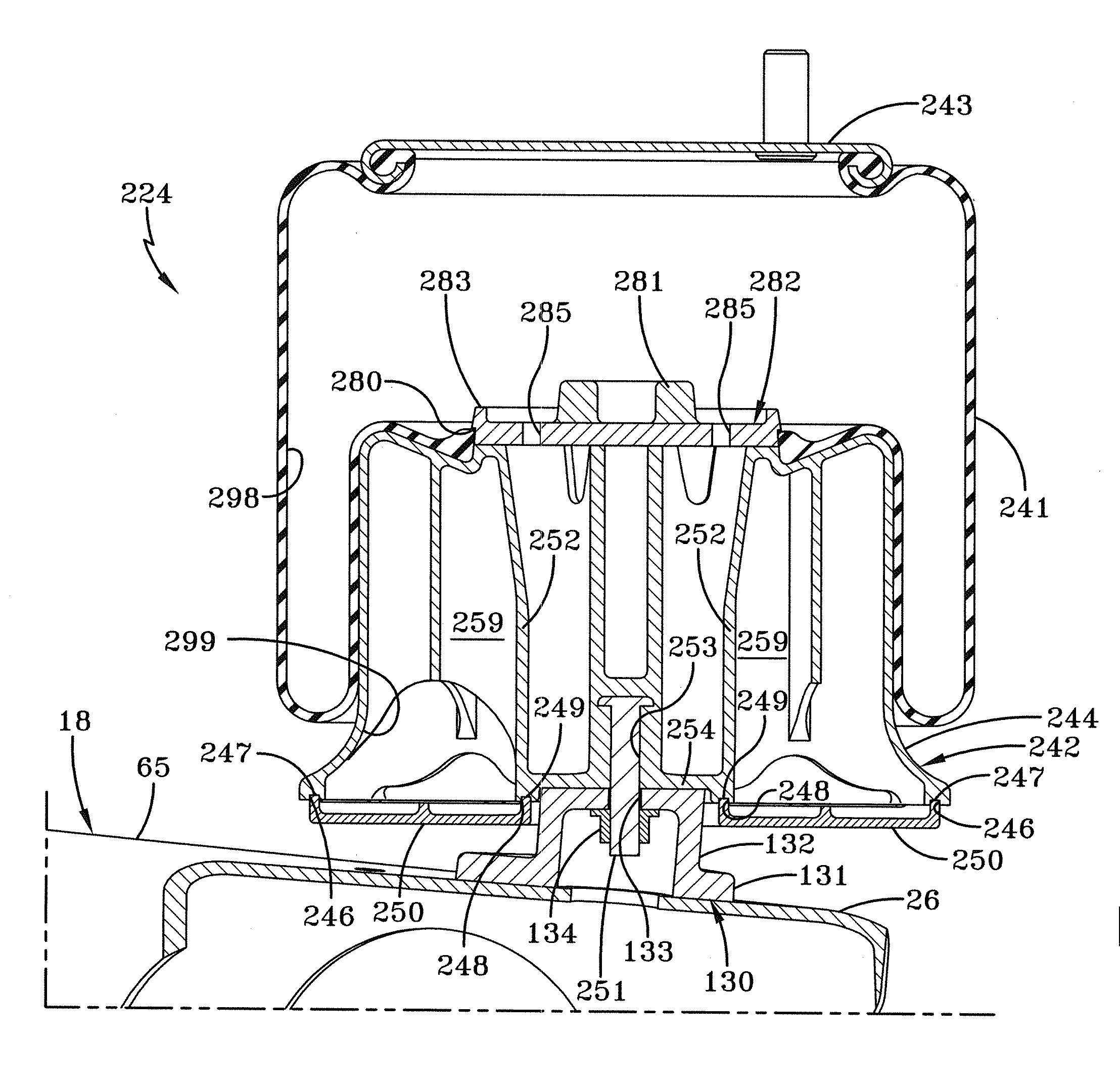
[0013]Objectives of the present invention include providing a piston for an air spring of a heavy-duty vehicle that is more efficient and simple to manufacture and that reduces manufacturing costs.

Problems solved by technology

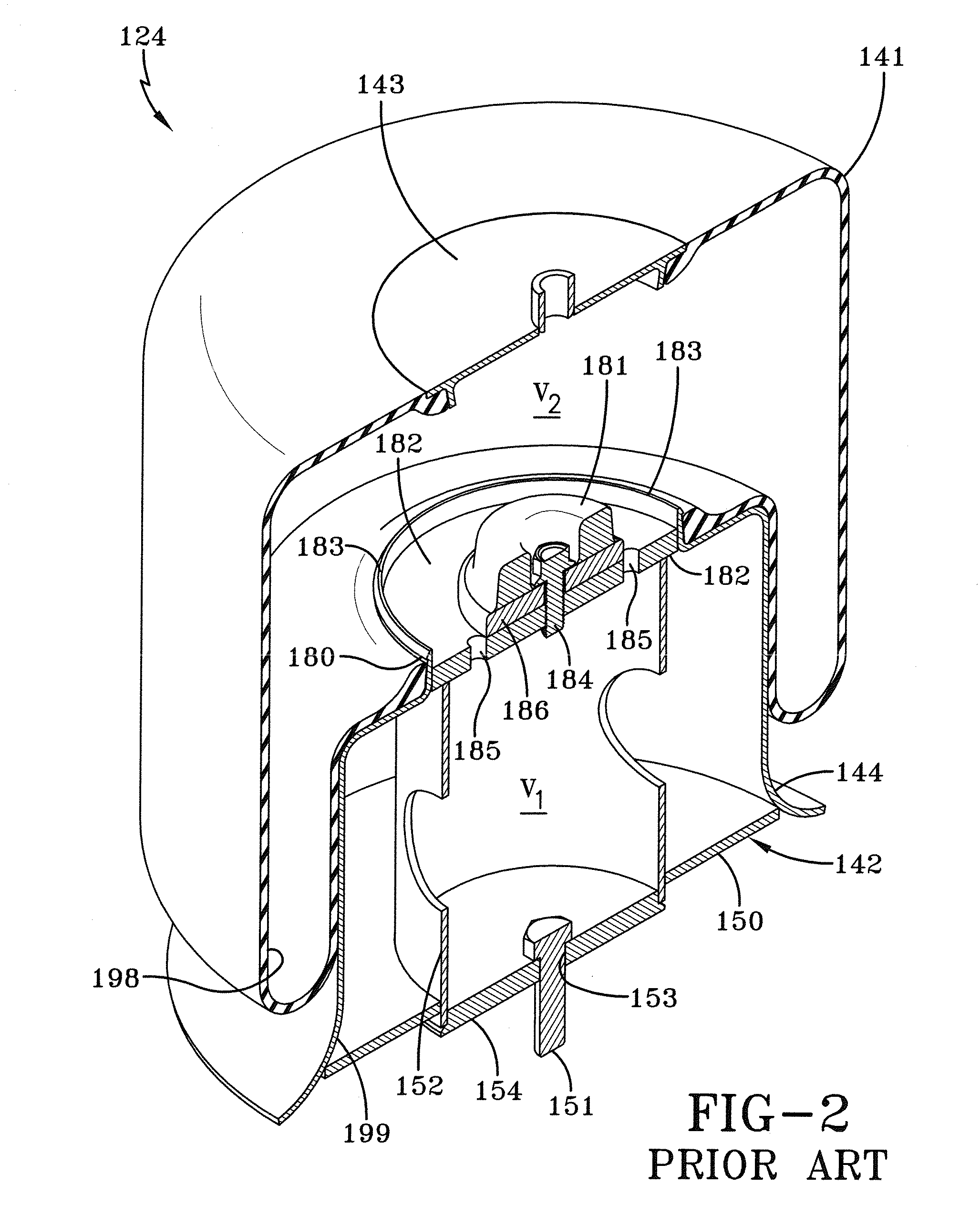
Because the prior art air spring piston typically has a relatively complex integral one-piece structural design, manufacture of the piston from composite materials can be complicated.
More particularly, because the lip or barb is integrally formed in one piece on the upwardly extending protrusion, which in turn is integrally formed in one piece with the top plate of the piston, manufacture of the piston from composite materials can be quite complex and therefore inefficient, as is well known to those of ordinary skill in the art.
In addition, because the bottom plates of the piston and the central hub, respectively, are generally flat, the volume contained in the piston is generally limited because of spatial limitations between the beam of the suspension assembly and the main member of the vehicle.

Method used


Image

  • Piston for an air spring of a heavy-duty vehicle
  • Piston for an air spring of a heavy-duty vehicle
  • Piston for an air spring of a heavy-duty vehicle

Examples


Embodiment Construction

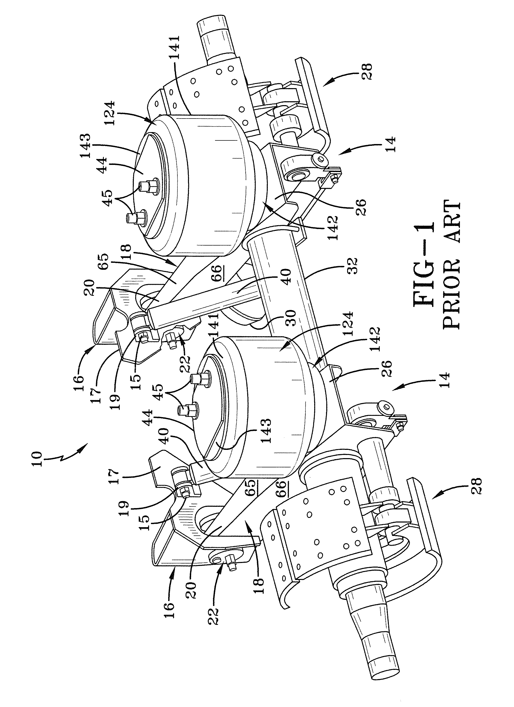
[0028]In order to better understand the environment in which the air spring piston for heavy-duty vehicles of the present invention is utilized, a trailing arm overslung beam-type air-ride axle / suspension system that incorporates a prior art heavy-duty vehicle trailer air spring 124, is indicated generally at 10, is shown in FIG. 1, and now will be described in detail below.

[0029]It should be noted that axle / suspension system 10 is typically mounted on a pair of longitudinally-extending spaced-apart main members (not shown) of a heavy-duty vehicle, which is generally representative of various types of frames used for heavy-duty vehicles, including primary frames that do not support a subframe and primary frames and / or floor structures that do support a subframe. For primary frames and / or floor structures that do support a subframe, the subframe can be non-movable or movable, the latter being commonly referred to as a slider box. Because axle / suspension system 10 generally includes a...


PUM


Abstract

A piston for an air spring of a heavy-duty vehicle includes a sidewall and a central hub. The sidewall and the central hub are attached to a first bottom plate of the piston. A top plate is removeably attached to a top portion of the sidewall and a top portion of the central hub. A bottom portion of said central hub includes a second bottom plate that is recessed relative to the first bottom plate for attachment to a piston mounting pedestal that is in turn mounted to a beam of a suspension assembly of the heavy-duty vehicle.

Description

CROSS-REFERENCE TO RELATED APPLICATION[0001]This application claims the benefit of U.S. Provisional Patent Application Ser. No. 61 / 486,857, filed May 17, 2011.BACKGROUND OF THE INVENTION[0002]1. Field of the Invention[0003]The invention relates generally to the art of axle / suspension systems for heavy-duty vehicles. More particularly, the invention relates to air-ride axle / suspension systems for heavy-duty vehicles, which utilize an air spring to cushion the ride of the vehicle. More specifically, the invention is directed to a piston for an air spring of a heavy-duty vehicle air-ride axle / suspension system, in which the air spring piston upper portion is formed in two parts, including a top plate and a continuous stepped sidewall. Forming the top plate as a discrete part from the continuous stepped sidewall allows for more efficient manufacture of the air spring piston. A downwardly extending piston bottom plate allows for increased piston volume, which in turn provides a reduced s...

Claims


Application Information

Patent Timeline
Patent Type & Authority Applications(United States)
IPC IPC(8): F16J1/09F16J1/00
CPCB60G9/003B60G11/27B60G2300/02F16F9/057F16J3/06
Inventor WESTNEDGE, ANDREW J.RUBALSKIY, DMITRY ENRIKOVICHKEELER, MICHAEL J.
Owner HENDRICKSON USA L L C
Why Eureka
Try Eureka