Mask system and method of patterning magnetic media

a mask system and magnetic media technology, applied in the field of magnetic storage, can solve the problems of limiting the ability to magnetically write features of the size required to meet the storage density target, affecting the planarity of the feature, and affecting the success of the target implementation

Inactive Publication Date: 2012-11-22
VARIAN SEMICON EQUIP ASSOC INC
View PDF4 Cites 10 Cited by
  • Summary
  • Abstract
  • Description
  • Claims
  • Application Information

AI Technical Summary

Benefits of technology

[0010]Embodiments of the present invention are directed to methods and systems for improving patterning a substrate, in particular, by patterning a magnetic medium. In one embodiment, a method of patterning a substrate comprises patterning a resist layer disposed on the substrate using imprint lithography and etching exposed portions of a hard mask layer disposed between the patterned resist layer and the substrate. The method further comprises implanting ions into a magnetic layer in the substrate while the etched hard mask layer is disposed thereon.

Problems solved by technology

As storage density scales to the Tbit / in2 range, microstructural limitations in blanket magnetic films, such as grain size effects, may limit the ability to magnetically write features of the size required to meet the storage density target.
Although the nano-imprint lithography and related processes can in principle produce small isolated structures on the scale of tens of nm in lateral dimension, several challenges to its successful implementation remain.
The aforementioned process steps involve removal of magnetic material, which may redeposit in other regions of the substrate, which may degrade planarity and may lead to damage of the sidewalls of bits during etch removal.
In addition, it may be desirable or necessary to planarize the substrate after the isolated islands of magnetic material are created, adding to process complexity.
However, the stencil mask efforts have involved relatively large bit patterns, where the lateral feature size is on the order of one micrometer, which is not suitable for future storage density requirements.
However, photoresist materials generally exhibit less than optimal stability when subject to ion implantation.
This instability may limit the ability to pattern very small dimensions using photoresist as an implantation mask.

Method used


Image

  • Mask system and method of patterning magnetic media
  • Mask system and method of patterning magnetic media
  • Mask system and method of patterning magnetic media

Examples


Embodiment Construction

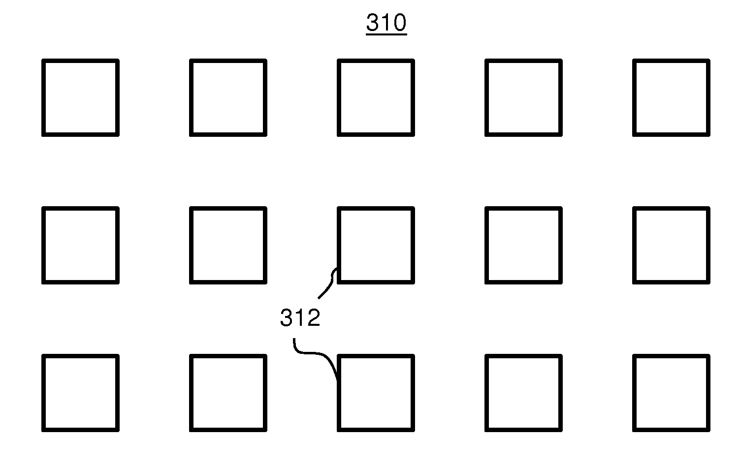
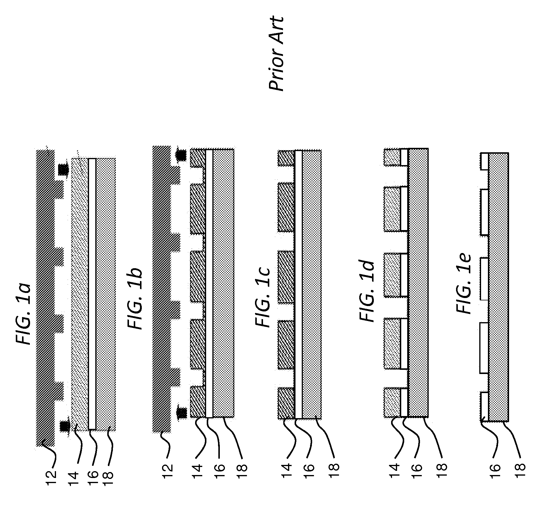
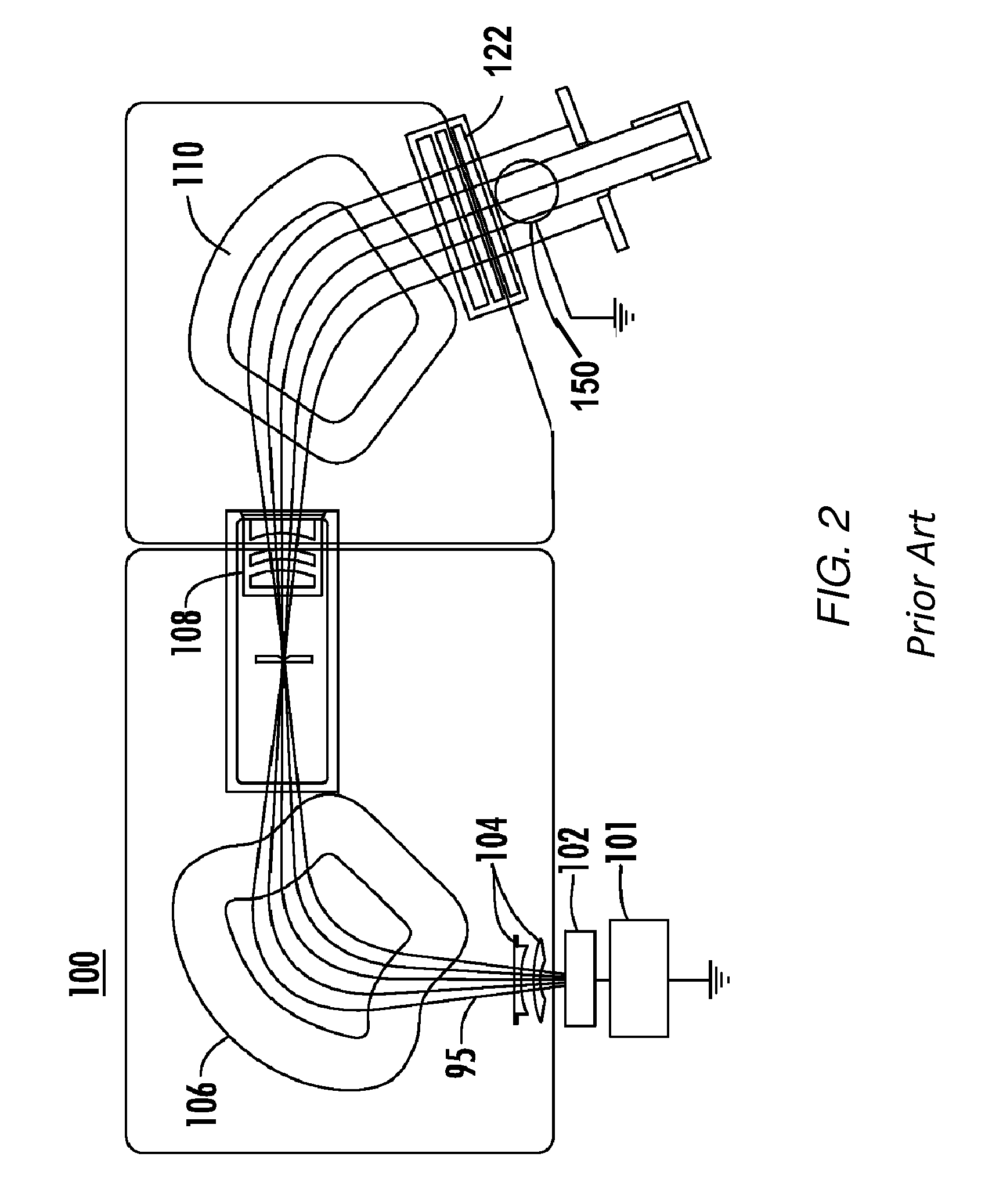
[0018]The present invention will now be described more fully hereinafter with reference to the accompanying drawings, in which preferred embodiments of the invention are shown. This invention, however, may be embodied in many different forms and should not be construed as limited to the embodiments set forth herein. Rather, these embodiments are provided so that this disclosure will be thorough and complete, and will fully convey the scope of the invention to those skilled in the art. In the drawings, like numbers refer to like elements throughout.

[0019]To solve the deficiencies associated with the methods noted above, novel and inventive techniques and systems for patterning a substrate are introduced. In particular, the present disclosure focuses on techniques involving ion implantation processes for patterning magnetic media. The methods disclosed herein may be used in conjunction with lithography processes including nano-imprint patterning. However, those of ordinary skill in th...


PUM

PropertyMeasurementUnit
widthaaaaaaaaaa
thicknessaaaaaaaaaa
specific gravityaaaaaaaaaa

Abstract

A method of patterning a substrate, comprises patterning a photoresist layer disposed on the substrate using imprint lithography and etching exposed portions of a hard mask layer disposed between the patterned photoresist layer and the substrate. The method may also comprise implanting ions into a magnetic layer in the substrate while the etched hard mask layer is disposed thereon.

Description

BACKGROUND OF THE INVENTION[0001]1. Field of the Invention[0002]Embodiments relate to the field of magnetic storage. More particularly, the present invention relates to a method, system and structure for patterning a magnetic substrate using ion implantation.[0003]2. Discussion of Related Art[0004]Conventional magnetic storage media may be fabricated using blanket magnetic layers that are written and read using a magnetic device to create and / or read small magnetic domains within the layer. As storage density scales to the Tbit / in2 range, microstructural limitations in blanket magnetic films, such as grain size effects, may limit the ability to magnetically write features of the size required to meet the storage density target. As an alternative to conventional magnetic storage coatings, bit patterned magnetic media have been studied in recent years.[0005]In bit patterned magnetic recording media, individual islands of magnetic material may be isolated from one another, such that ea...

Claims


Application Information

Patent Timeline
Patent Type & Authority Applications(United States)
IPC IPC(8): G11B5/84C23C14/48C23C14/04
CPCG11B5/855
Inventor KONTOS, ALEXANDER C.SINCLAIR, FRANKRENAU, ANTHONY
Owner VARIAN SEMICON EQUIP ASSOC INC
Why Eureka
Try Eureka