
Thermally-conductive vibration isolators and spacecraft isolation systems employing the same

a technology of thermal conductivity and isolator, which is applied in the field of thermal conductivity vibration isolators, can solve the problems of increasing the ambient temperature range, reducing the lifespan of hardware, and reducing the heat generation of the attitude adjustment payload during operation, so as to minimize the transmission of vibrations

Inactive Publication Date: 2012-11-22
HONEYWELL INT INC
View PDF10 Cites 21 Cited by
  • Summary
  • Abstract
  • Description
  • Claims
  • Application Information

AI Technical Summary

Benefits of technology

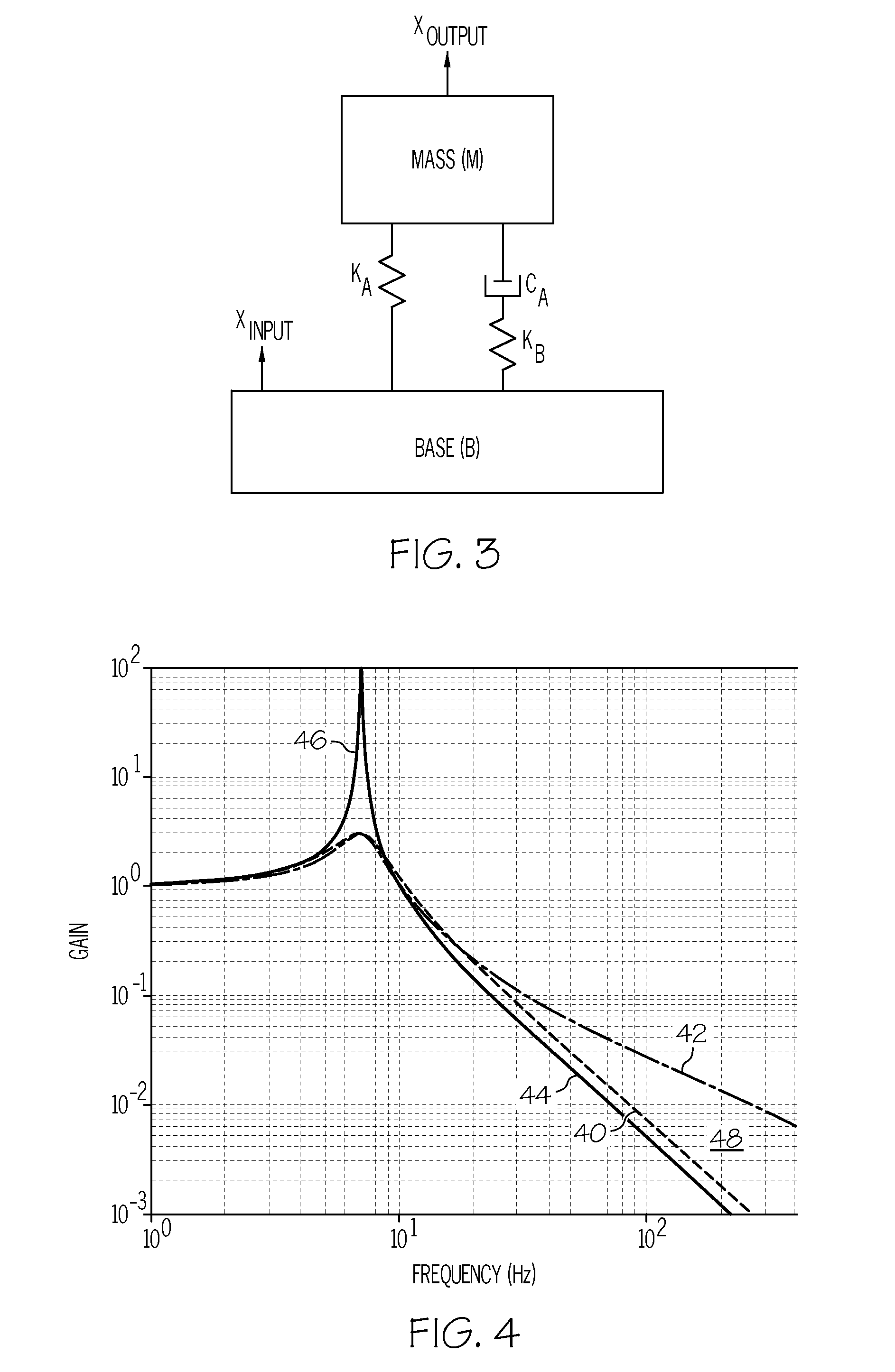
[0007]Embodiments of a spacecraft isolation system for minimizing the transmission of vibrations between a spacecraft and a payload are further provided. In one embodiment, the spacecraft isolation system includes a plurality of thermally-conductive vibration isolators and mounting hardware coupled to plurality of thermally-conductive vibration isolators. Each of the thermally-conductive vibration isolators includes a first end portion, a second end portion substantially opposite the first end portion, and first and second load transfer paths from the first end portion to the second end portion. The first load transfer path includes a main spring. The second load transfer path includes a secondary spring in parallel with the main spring, as well as a damper in parallel with the main spring and in series with the secondary spring. Each of the thermally-conductive vibration isolators further includes an elongated heat pipe, which, in turn, includes an elongated body and at least one bellows section coupled to the elongated body. The elongated body of the heat pipe extends from the first end portion to the second end portion through each of the main spring, the secondary spring, and the damper. The at least one bellows section imparts the elongated heat pipe with an axial stiffness less than the axial stiffness of the main spring and less than the cumulative axial stiffness of the secondary spring and the damper.

Problems solved by technology

In addition to producing vibrations, attitude adjustment payloads also tend to produce excessive amounts of heat during operation due, at least in part, to frictional forces at rotary interfaces and thermal inefficiencies inherent in electronics.
If not adequately dissipated, the excess heat generated by a spacecraft payload can decrease the lifespan of hardware, increase the ambient temperature range to undesirable levels, and, in severe cases, result in equipment failure.
A limited amount of excess heat may be removed from a payload by radiation; however, radiative heat transfer is generally inadequate to provide sufficient dissipation of heat in the case of payloads, such as larger control moment gyroscope arrays and reaction wheels arrays, having a relatively large thermal output.
While radiative heat transfer can be improved by increasing the cumulative surface area of spacecraft-mounted parts in view of the heated payload surfaces (referred to as the “radiative view factor”), such a practice adds undesirable weight and bulk to the spacecraft and may still fail to provide adequate heat dissipation.
However, as the dimensions of a heat strap increase, so too do the weight and stiffness of the heat strap.
While providing excellent thermal conduction paths for payload heat dissipation, heat straps having larger cross-sectional areas tend to be undesirably bulky and weighty for deployed onboard a spacecraft.
More importantly, heat straps having larger cross-sectional areas tend to be relatively stiff and may shunt vibratory forces around the vibrational isolators directly to the spacecraft body thereby partially defeating the effectiveness of the vibrational isolation system.

Method used


Image

  • Thermally-conductive vibration isolators and spacecraft isolation systems employing the same
  • Thermally-conductive vibration isolators and spacecraft isolation systems employing the same
  • Thermally-conductive vibration isolators and spacecraft isolation systems employing the same

Examples


Embodiment Construction

[0013]The following Detailed Description is merely exemplary in nature and is not intended to limit the invention or the application and uses of the invention. Furthermore, there is no intention to be bound by any theory presented in the preceding Background or the following Detailed Description.

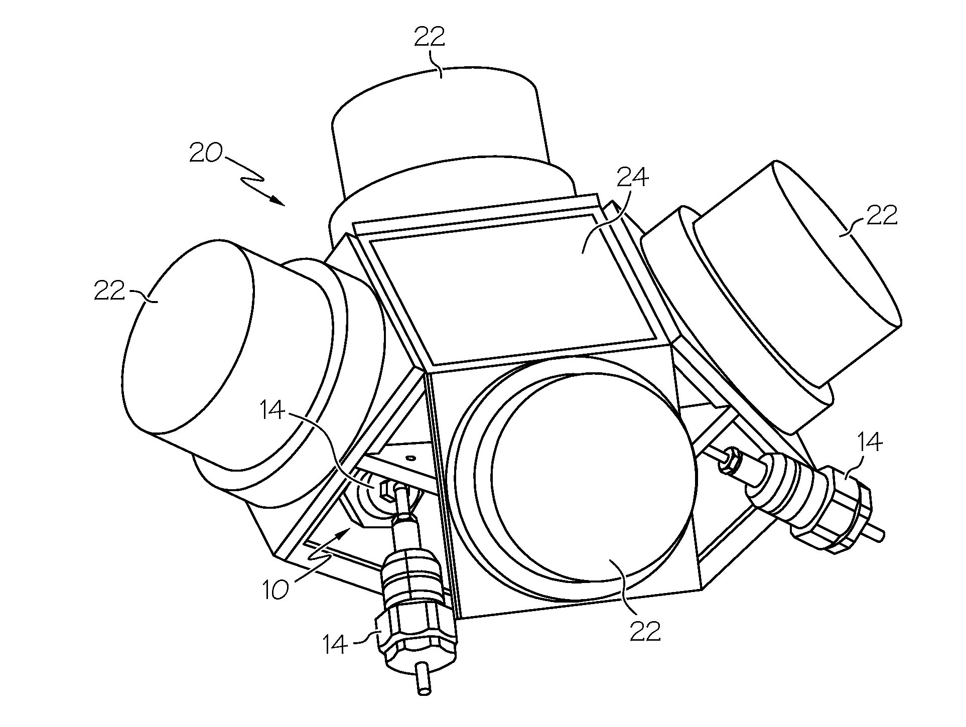
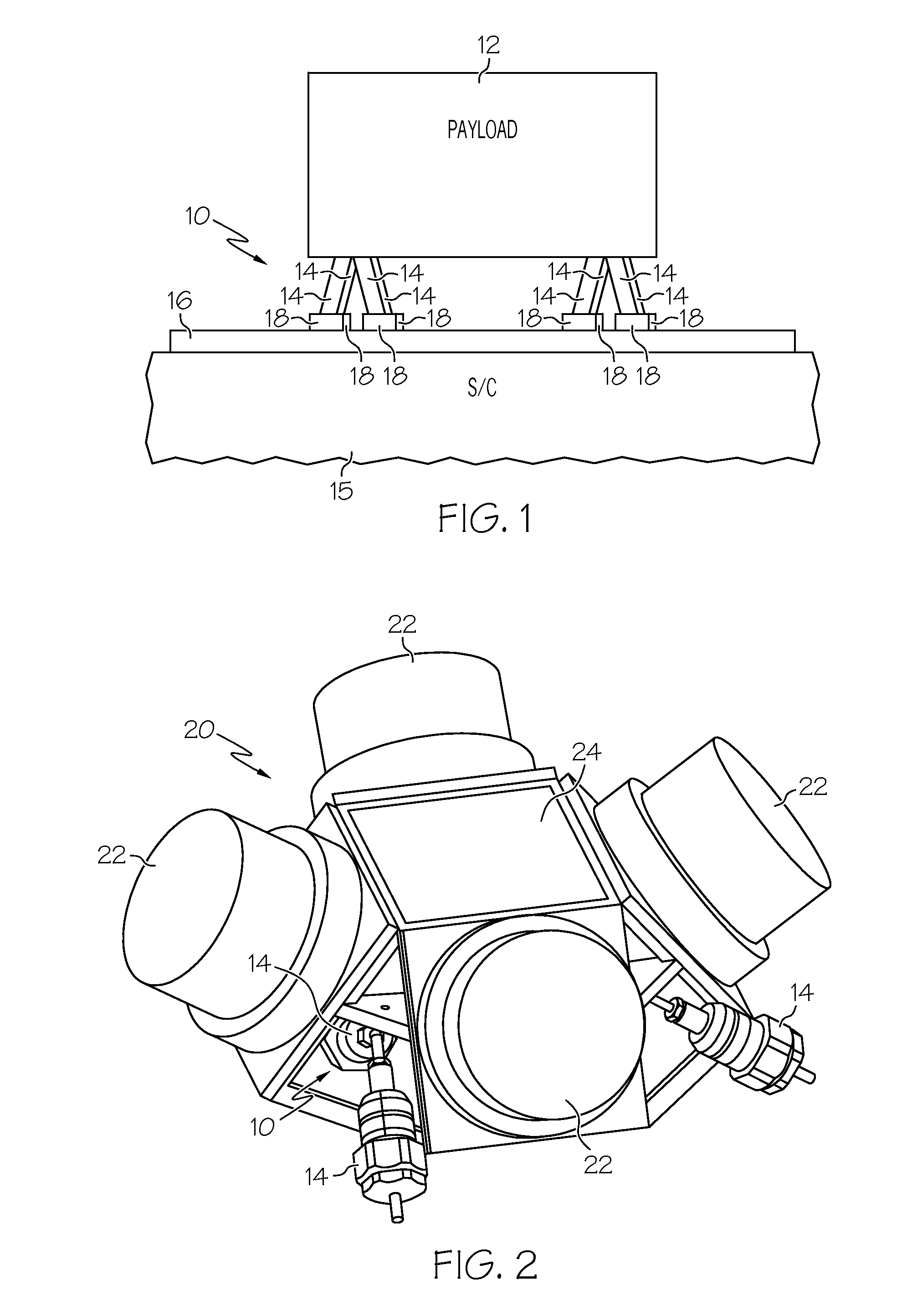
[0014]FIG. 1 is simplified schematic of a vibration isolation system 10 illustrated in accordance with an exemplary embodiment of the present invention and well-suited for reducing the transmission of vibrations between a payload 12 and a host spacecraft 15. In the illustrated example, isolation system 10 includes a plurality of single degree of freedom or axially-damping vibration isolators 14, which are mechanically coupled to and collectively support payload 12. The opposing ends of isolators 14 are mounted to a spacecraft mounting interface 16 utilizing a plurality of mounting brackets 18. In this particular example, isolation system 10 includes eight vibration isolators 14, which are po...


PUM


Abstract

Embodiments of a thermally-conductive vibration isolator are provided, as are embodiments of a spacecraft isolation employing a plurality of thermally-conductive vibration isolators. In one embodiment, the thermally-conductive vibration isolator includes a first end portion, a second end portion substantially opposite the first end portion, and first and second load transfer paths from the first end portion to the second end portion. The first and second load transfer paths comprise a main spring and a damper in parallel with the main spring, respectively. An elongated thermal conduit, which has a thermal conductivity exceeding that of first load transfer path and the second load transfer path, extends from the first end portion to the second end portion.

Description

TECHNICAL FIELD[0001]The present invention relates generally to spacecraft isolation systems and, more particularly, to embodiments of a thermally-conductive vibration isolator, as well as to embodiments of a spacecraft isolation system employing a plurality of thermally-conductive vibration isolators.BACKGROUND[0002]Control moment gyroscope arrays, reaction wheel arrays, and other such deployed onboard spacecraft for attitude adjustment purposes generate vibratory forces during operation. Vibration isolation systems may be deployed between such attitude adjustment payloads and the spacecraft body to minimize the transmission of vibratory forces to the spacecraft body and any vibration-sensitive components (e.g., optical payloads) carried thereby. A typical vibration isolation system includes a number of individual vibrations isolators (typically three to eight isolators), which are positioned between the spacecraft payload and the spacecraft body in a multi-point mounting arrangeme...

Claims


Application Information

Patent Timeline
IPC IPC(8): F16F15/023F16M13/00F16F15/04
CPCB64G1/283B64G1/285F16F15/022B64G1/641F16F9/20B64G1/286B64G1/6425
Inventor SMITH, DENNIS WAYNEHADDEN, STEVEN
Owner HONEYWELL INT INC
Learn More