High resolution high contrast edge projection

a high contrast, edge technology, applied in the field of high contrast edge projection, can solve the problems of expensive equipment for analog systems known in the art, and achieve the effect of low cos

Active Publication Date: 2012-11-22
NAT RES COUNCIL OF CANADA
View PDF4 Cites 18 Cited by
  • Summary
  • Abstract
  • Description
  • Claims
  • Application Information

AI Technical Summary

Benefits of technology

[0010]For those wanting to project a high definition high contrast edges on a screen, or object, or within a 3D volume, as is currently desired at least for various surface or volume illuminating techniques, and metrology (fringe projection systems are particularly noted), there is a need for a low cost solution, especially if multiple different patterns of illumination with different edges are desired. Analog systems known in the art require expensive equipment because of the stringent alignment / registration requirements of the moving parts.

Problems solved by technology

Analog systems known in the art require expensive equipment because of the stringent alignment / registration requirements of the moving parts.

Method used


Image

  • High resolution high contrast edge projection
  • High resolution high contrast edge projection
  • High resolution high contrast edge projection

Examples


example

Lower Cost System (Prophetic Example)

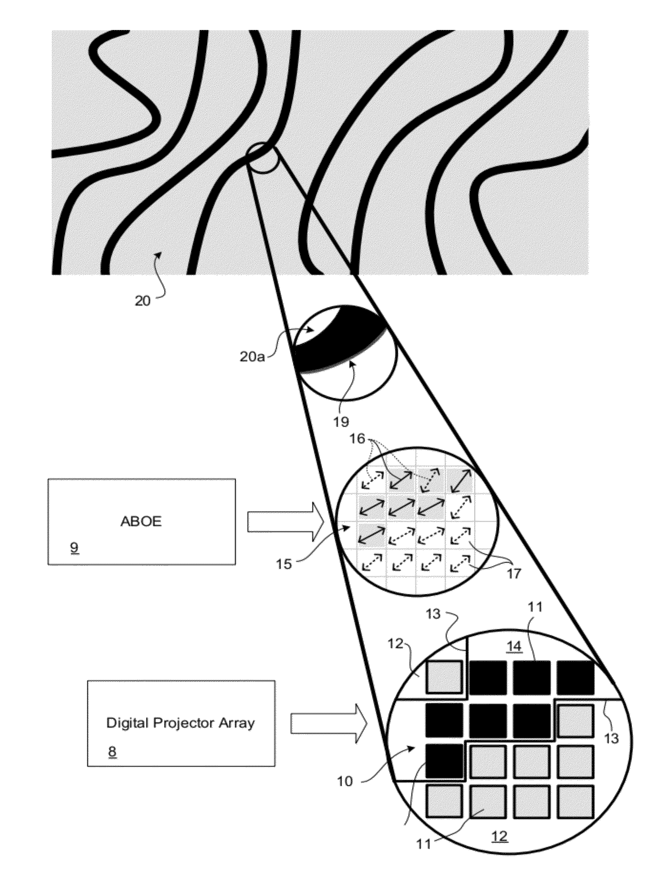
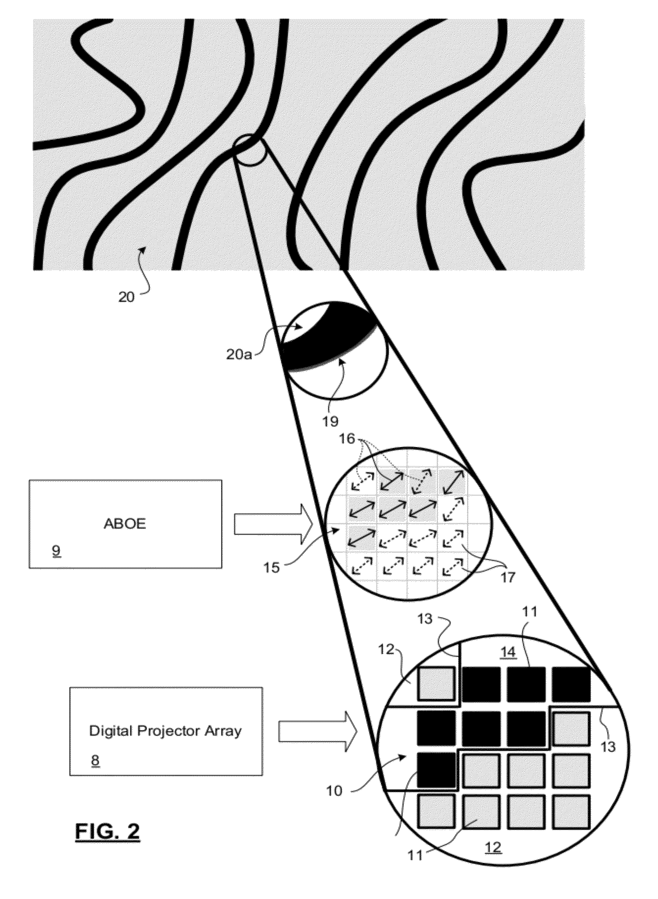
[0051]A Projector: Proxima ultra light×350 which contains a digital video interface card and a DMD chip. For best results, a colour wheel of the projector can be removed, as this provides a brightest illumination. A convex cylindrical lens with a focal length of 150 mm can be placed in front of the projector at 4 mm from the projection lens, parallel with the projection lens. An angle between the cylindrical lens' axis and the edges of the DMD mirrors is chosen, for example to be other than 0-2°, 88-92° or 178-180°, such as 8°. A procedure for cycling through illumination image instructions and evaluating the projected images until optimal images are identified is performed to calibrate the system. Thereafter images with linear (skew from the pixel axes) by the 8° will be blurred to provide lines with edges that have much higher contrast and resolution than can be produced with blurred projections of the same projector.

Higher Quality Projection S...


PUM


Abstract

Generating a high definition projected illumination pattern from a substantially lower resolution digital projector array involves: selectively illuminating a connected set of pixels to produce a pixellated, high contrast edge feature, and positioning an anisotropically blurring optical element (ABOE) between a light source of the projector array and the projection. The ABOE applies an anisotropic blur pattern to pixels of the at least one connected set, to locally preferentially blur the pixel more (and preferably substantially only) in a direction of equally or more strongly illuminated pixels, and not in directions of less illuminated pixels. Preferably a contour of the connected set has no beginning or end within a periphery of the illumination plane, and has bounded curvature, permitting simple ABOEs to be used. Several images each having several or many edges can be produced using a same ABOE. The ABOE may alleviate interpixel gap effects for non-edge pixels too.

Description

FIELD OF THE INVENTION[0001]The present invention relates in general to a technique for increasing a smoothness, resolution and uniformity of an edge in a projected high contrast image, using a lower resolution, pixellated, projector. The technique may be applied to spatially distribute light in a pattern with such edges, e.g. a pattern or texture for such applications as metrology, and structured light (fringe) projection systems.BACKGROUND OF THE INVENTION[0002]There are various systems that project patterns of light. Special purpose projectors are designed to generate a relatively small number of light patterns, but to provide a quality of illumination that is higher than general purpose projectors, which are designed to project any image. Such projectors may have application in structured light (fringe) projection systems, macroscopic photoresist exposure systems, or thermal pattern deposition systems for example, where the projection is applied to a surface, and the pattern def...

Claims


Application Information

Patent Timeline
Patent Type & Authority Applications(United States)
IPC IPC(8): H04N5/225G02B3/06G09G5/10G02B5/00
CPCG02B3/08G02B3/06H04N9/3188G01B11/2513H04N9/317G02B3/005G02B27/18G03B21/13
Inventor DROUIN, MARC-ANTOINEBLAIS, FRANCOIS
Owner NAT RES COUNCIL OF CANADA
Why Eureka
Try Eureka