Percutaneous Mitral Annulus Mini-Plication

a technology of mitral valve and annulus, which is applied in the field of mitral valve regurgitation treatment devices and methods, can solve the problems of mitral valve regurgitation, weakened, damaged, and dilated valve annulus, so as to shorten the circumference of the annulus and reduce the regurgitation of the valv

Inactive Publication Date: 2012-11-22
BOSTON SCI SCIMED INC
View PDF2 Cites 134 Cited by
  • Summary
  • Abstract
  • Description
  • Claims
  • Application Information

AI Technical Summary

Benefits of technology

[0008]The present apparatus for percutaneous plication of a valve assembly (such as the mitral valve annulus in order to reduce valve regurgitation) reduces the annulus by placing at least one plication clip around the valve annulus, each clip shortening the circumference of the annulus.
[0010]In at least one embodiment, an assembly for percutaneus plication of a valve assembly is provided. In at least one embodiment, the assembly comprises at least one plication clip and a delivery device. In at least one embodiment, the delivery device has a proximal end and a distal end. In at least one embodiment, the delivery device comprises at least a retaining mechanism and a shaft. The clip has a loaded state when the clip is loaded onto the delivery device and the clip has a deployed state when the clip is released from the delivery device. When the clip is in the loaded state, the clip has a distance between the first end and the second end. When the clip is in the deployed state, the central portion has a curvilinear profile that shortens the distance between the first end and the second end.

Problems solved by technology

Thus, mitral valve regurgitation may decrease the heart's pumping efficiency, sometimes significantly.
A number of mechanical defects of the mitral valve and the left ventricle may cause mitral valve regurgitation.
The valve annulus may be dilated, weakened, or damaged.
The valve leaflets may be prolapsed, displaced, or damaged such that they do not close properly.
Further, the valve chordae, the papillary muscles, or the left ventricular wall may be damaged or weakened.
While these devices and methods of repairing the valve are effective, they typically require open heart surgery, which is a highly invasive procedure.
However, these procedures may be less desirable or less effective due to the anatomy of the coronary sinus, the mitral annulus, and the nearby circumflex coronary artery.
In particular, by placing a rigid annular cinching device in the coronary sinus, the coronary sinus may cross over the circumflex coronary artery, which may cause compression of the coronary artery.

Method used


Image

  • Percutaneous Mitral Annulus Mini-Plication
  • Percutaneous Mitral Annulus Mini-Plication
  • Percutaneous Mitral Annulus Mini-Plication

Examples


Embodiment Construction

[0025]While this invention may be embodied in many different forms, there are described in detail herein specific preferred embodiments of the invention. This description is an exemplification of the principles of the invention and is not intended to limit the invention to the particular embodiments illustrated.

[0026]For the purposes of this disclosure, like reference numerals in the figures shall refer to like features unless otherwise indicated.

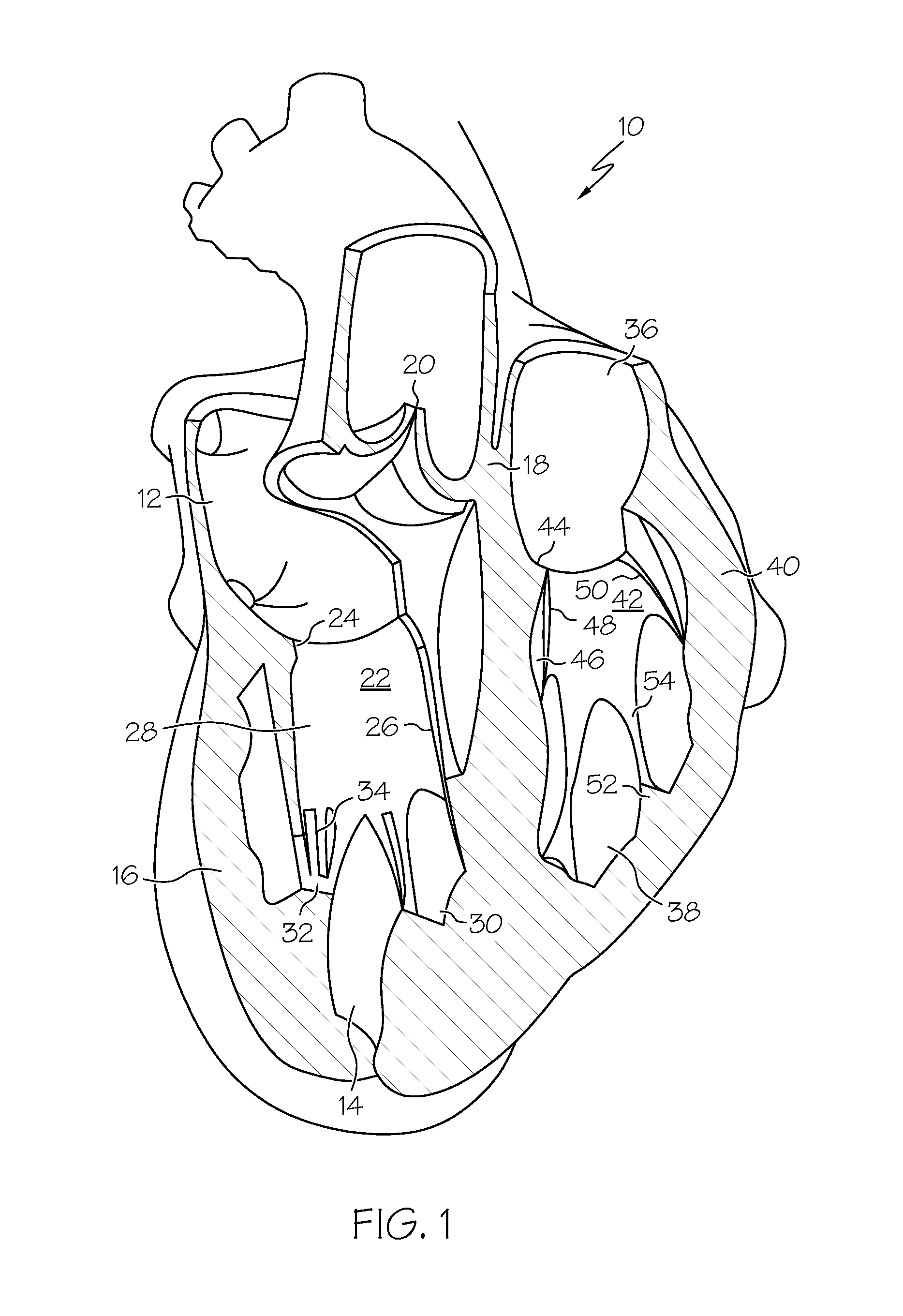
[0027]FIG. 1 shows a cross-sectional depiction of a normal human heart 10. The left side of the heart 10 (shown in FIG. 1) includes left atrium 12, left ventricular chamber 14 positioned between left ventricular wall 16 and septum 18, aortic valve 20, and mitral valve assembly 22. The components of the mitral valve assembly 22 include the mitral valve annulus 24, anterior leaflet 26 (sometimes referred to as the aortic leaflet because it is adjacent to the aortic region), posterior leaflet 28, two papillary muscles 30 and 32, and multiple c...


PUM


Abstract

A plication clip comprises a first end portion; a second end portion; and a central portion connecting the first end portion to the second end portion. The first end portion is curved toward the second end portion, and the second end portion is curved toward the first end portion. The central portion has a curvilinear profile such that when the clip is deployed, a shorter length between the first end portion and the second end portion is formed. A delivery catheter and methods for deploying the plication clip are also provided.

Description

CROSS REFERENCE TO RELATED APPLICATIONS[0001]This application claims the benefit of U.S. Provisional Application No. 61 / 487,065, entitled, “Percutaneous Mitral Annulus Mini-Plication,” by Scott R. Smith and Mark L. Jenson, and filed on May 17, 2011, the entire contents of which being incorporated herein by reference.BACKGROUND OF THE INVENTION[0002]The present invention relates generally to devices and methods for the treatment of regurgitation of the mitral valve, which is essentially a check valve located between the left atrium and the left ventricle of the heart. Mitral valve regurgitation occurs when the heart's mitral valve does not close properly. When this occurs, oxygenated blood can flow backwards from the left ventricle into the left atrium during systole, rather than flowing into the aorta and out to the rest of the body. Thus, mitral valve regurgitation may decrease the heart's pumping efficiency, sometimes significantly.[0003]A number of mechanical defects of the mitra...

Claims


Application Information

Patent Timeline
Patent Type & Authority Applications(United States)
IPC IPC(8): A61B17/08A61B17/10
CPCA61B17/00234A61B17/0644A61B17/1227A61F2/2442A61B2017/00243A61B2017/081A61B17/1285
Inventor SMITH, SCOTT R.JENSON, MARK L.
Owner BOSTON SCI SCIMED INC
Why Eureka
Try Eureka