Unified Rolling and Bending Process for Roller Bearing Cages

a technology of roller bearing cages and rolling bending, which is applied in the direction of mechanical equipment, rotary machine parts, engine components, etc., can solve the problems of frequent design changes, high cost, and large thickness of the cage, and achieve the effect of reducing the thickness

Active Publication Date: 2012-11-29
THE TIMKEN CO
View PDF26 Cites 10 Cited by
  • Summary
  • Abstract
  • Description
  • Claims
  • Application Information

AI Technical Summary

Benefits of technology

[0008]Briefly stated, the present disclosure provides a method for manufacturing tapered roller bearing cages, including large diameter tapered roller bearing cages, utilizing straight metal strips, coils, or plates as a raw material. The method begins by feeding a straight metal strip, coil, or plate (cage blank, hereinafter), precisely dimensioned in width, length and thickness, with or without windows or pockets pre-cut, into a rolling mill. The rolling mill incorporates a pair of unparallel forming rolls disposed such that a gap between the rolls is in a wedge configuration. As the cage blank is fed through the wedge-shaped forming roll gap, one side of the cage blank is plastically deformed to reduce its thickness and to elongate its length, while no deformation, or only a very slight deformation, is introduced to the other side of the cage blank. This introduces a linear and uniform reduction of the thickness from zero at one lateral edge to a predetermined amount at the other lateral edge. Thus the originally straight cage blank is formed into an arc shape. A third roll disposed on the exit side of the forming rolls, in a pre-calculated position, bends the rolled cage blank into a circular conical ring. After the entire cage blank is rolled into the conical ring, the conical ring may pass through the rolling mill one more time for a final resizing. The butt ends of the formed conical ring are joined together after any necessary trimming of the portions with inaccurate dimensional and geometric configurations, to form a completed large diameter tapered roller bearing cage.

Problems solved by technology

Manufacture of large tapered roller bearing cages, which are typically greater than 500 mm in diameter, is challenging work due to the fact that these bearing cages must meet high technical standards, are usually produced in low quantity, require large sized tools, and may be subject to frequent design changes.
Spinning is a cost intensive process requiring part-specific giant mandrels and tailstocks.
With increasing cage size, spinning becomes a prohibitive process due to the difficulty of locating a large enough blank for a mandrel to meet the required cage size.
The cost of large sized steel plates is also increased exponentially.
Similarly, ring rolling and machining processes for large cages are also very expensive.
Conventional methods for the manufacture of large diameter tapered roller bearing cages, such as spinning or ring rolling / machining processes are limited to working with materials having a maximum thickness, constrained by material formability and the tool load-carrying capacity of the forming process.

Method used


Image

  • Unified Rolling and Bending Process for Roller Bearing Cages
  • Unified Rolling and Bending Process for Roller Bearing Cages
  • Unified Rolling and Bending Process for Roller Bearing Cages

Examples


Embodiment Construction

[0022]The following detailed description illustrates the invention by way of example and not by way of limitation. The description enables one skilled in the art to make and use the present disclosure, and describes several embodiments, adaptations, variations, alternatives, and uses of the present disclosure, including what is presently believed to be the best mode of carrying out the present disclosure.

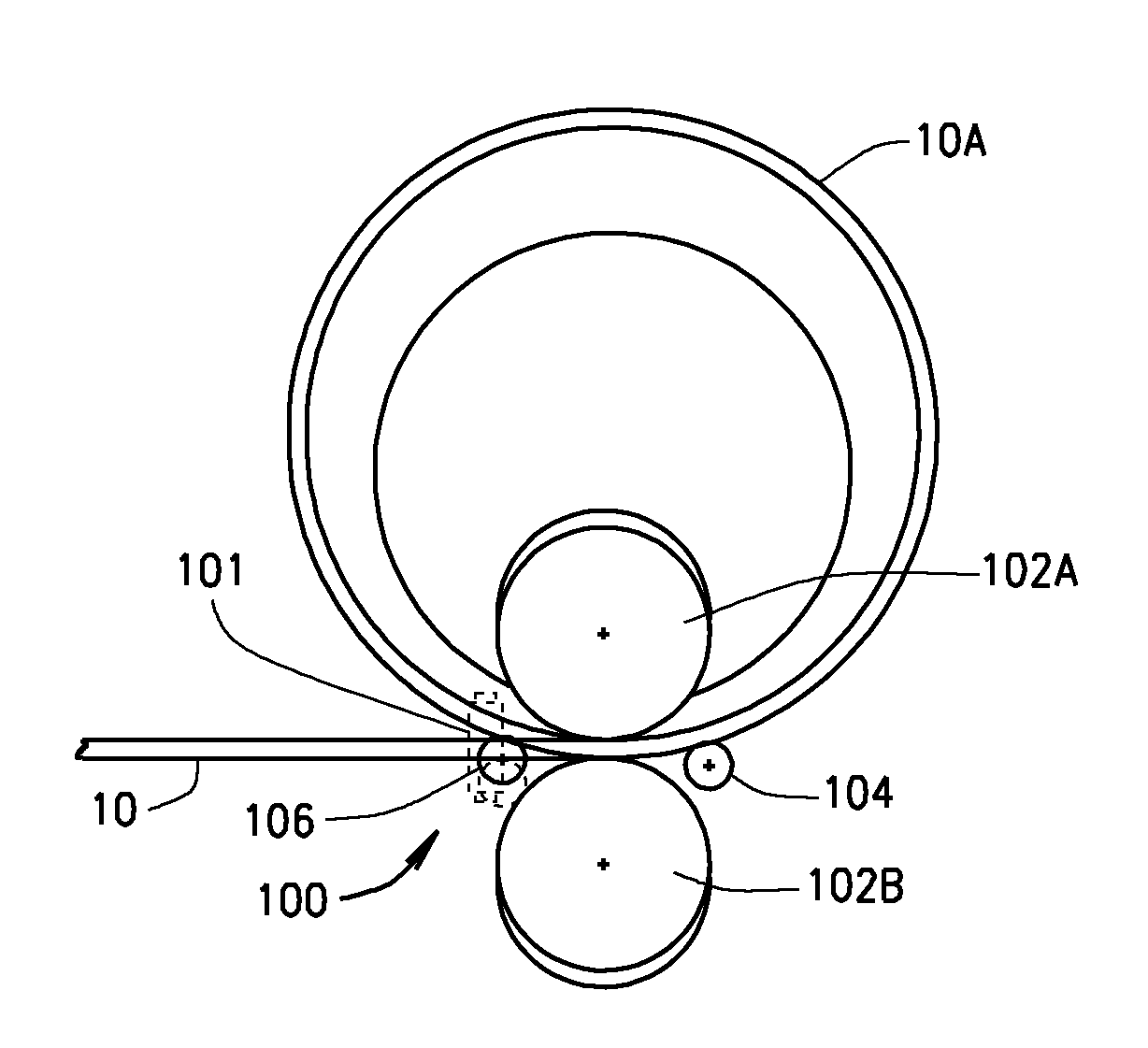
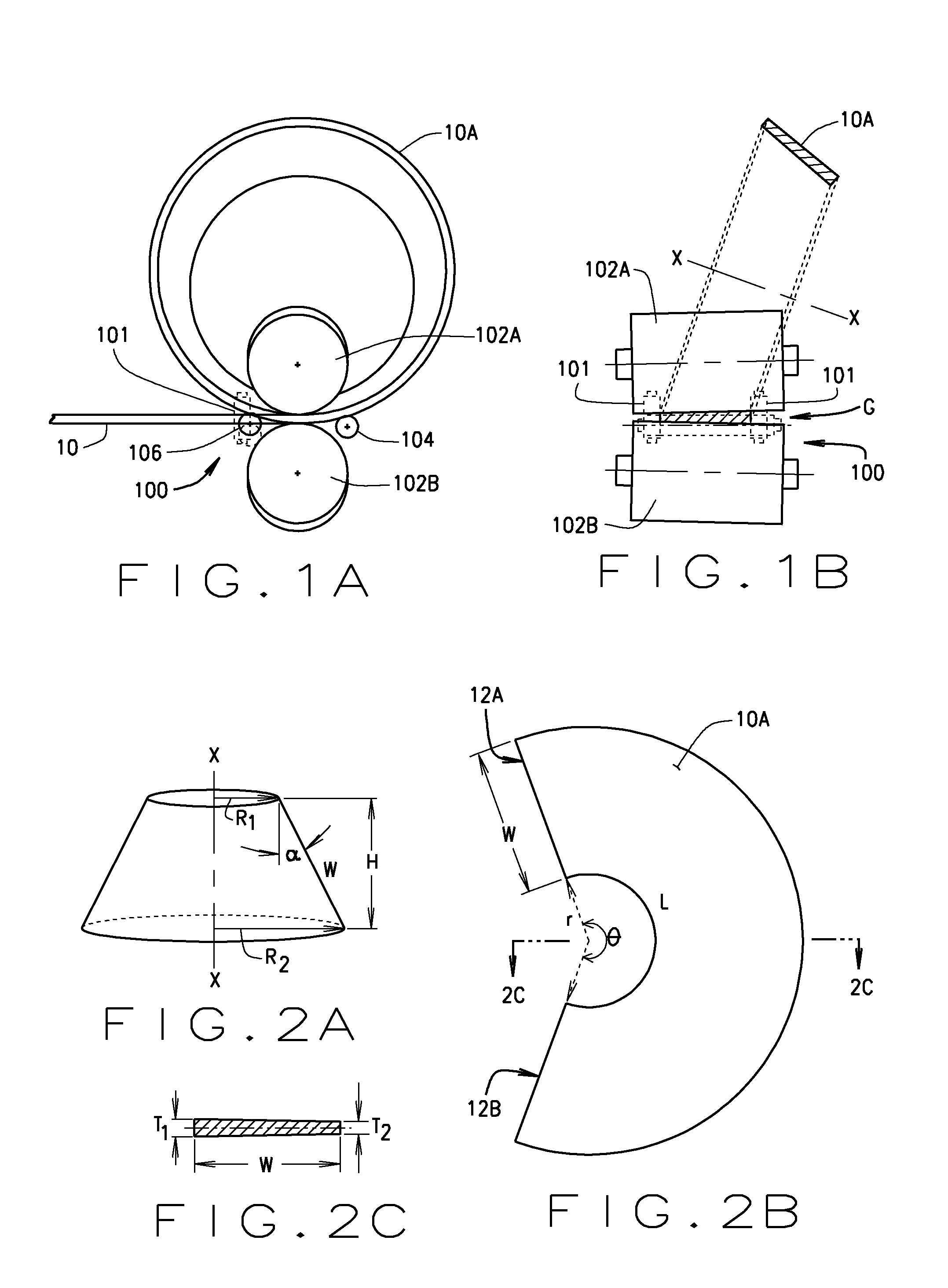
[0023]Turning to the figures, and to FIGS. 1A and 1B in particular, it is seen that a process of the present disclosure begins with a straight metal strip or plate (cage blank material (10), hereinafter), which has been precisely dimensioned in width, length and thickness. The cage blank material (10) may be formed from any suitable material, such as steel, and may include pre-cut windows or pockets (not shown) for receiving bearing rolling elements.

[0024]The windows or pockets on the cage to constrain the bearing rollers can be made before or after the cage is rolled, by a mechanic...


PUM

PropertyMeasurementUnit
internal diameteraaaaaaaaaa
diameteraaaaaaaaaa
widthaaaaaaaaaa

Abstract

A method for manufacturing large diameter tapered roller bearing cages (10B). A straight metal strip, coil or plate of cage blank material (10), precisely dimensioned in width, length and thickness, with or without windows or pockets pre-cut, is fed into a rolling mill (100). The rolling mill incorporates a pair of unparallel forming rolls (102A, 102B) disposed such that the gap (G) there between forms a wedge shape. As the cage blank material (10) is fed through the wedge-shaped forming roll gap (G), one lateral side of the cage blank material is plastically deformed to reduce its thickness (T) and to elongate its length, while no deformation or only a very slight deformation is introduced to the other lateral side of the cage blank, thus forming the cage blank into an arc shape. A third roll (104) disposed in exit side of the forming rolls (102), in a pre-calculated position, bends the rolled cage blank into a circular conical ring (10A). After the entire cage blank is rolled into the conical ring configuration, the conical ring may pass through the rolling mill (100) again for a final resizing. Adjacent butt ends (12A, 12B) of the formed conical ring cage blank (10A) are aligned and joined together during the assembly process to form the large diameter tapered roller bearing cage (10B).

Description

CROSS-REFERENCE TO RELATED APPLICATIONS[0001]The present application is related to, and claims priority from, U.S. Provisional Patent Application Ser. No. 61 / 300,175 filed on Feb. 1, 2010.STATEMENT REGARDING FEDERALLY SPONSORED RESEARCH[0002]Not Applicable.BACKGROUND OF THE INVENTION[0003]The present disclosure is related generally to methods for manufacturing large diameter tapered roller bearing cages, and in particular, to a method of manufacture for such tapered roller bearing cages which utilizes straight steel strip or plate material.[0004]Manufacture of large tapered roller bearing cages, which are typically greater than 500 mm in diameter, is challenging work due to the fact that these bearing cages must meet high technical standards, are usually produced in low quantity, require large sized tools, and may be subject to frequent design changes. Currently, large tapered roller bearing cages are produced by spinning or ring rolling / machining processes. Spinning is a cost inten...

Claims


Application Information

Patent Timeline
Patent Type & Authority Applications(United States)
IPC IPC(8): B21D53/12
CPCB21D5/08B21D5/12B21D5/14Y10T29/49643B21D53/12F16C33/543B21D11/08F16C19/364F16C2300/14Y10T29/49636Y10T29/49657Y10T29/49679Y10T29/49691F16C33/46
Inventor HE, MINGSIMMONS, MICHAEL D.
Owner THE TIMKEN CO
Why Eureka
Try Eureka