Exhaust system with heat accumulator

a technology of exhaust system and heat accumulator, which is applied in the direction of heat storage plant, lighting and heating apparatus, and station tubular conduit assembly, etc. it can solve the problems of limiting consuming fuel for operation, and reducing the efficiency of combustion engine for converting energy contained in fuel into mechanical energy, so as to minimize the dissipation of heat to the ambient air and minimize the effect of heat quantity

Inactive Publication Date: 2012-11-29
BENTELER AUTOMOBILTECHNIK GMBH
View PDF8 Cites 1 Cited by
  • Summary
  • Abstract
  • Description
  • Claims
  • Application Information

AI Technical Summary

Benefits of technology

[0023]According to another advantageous feature of the present invention, a thermal insulation can be formed on an outer surface area of the heat accumulator housing. Advantageously, the thermal insulation is a metal coating. As a result of thermal insulation on the outer side of the heat accumulator housing, heat dissipation to the ambient air is minimized. This ensures that the heat accumulator is able to optimally charge in the operating behavior and the stored heat quantity can be maintained over a longest possible time period without being wasted through dissipation to the ambient air. The thermal insulation may also be implemented in the form of a thermal insulating material, air gap insulation and / or in the form of a metallic film coating. In particular, it is possible to provide a reflection of heat energy in the heat accumulator by the surface of the metallic coating back into the heat accumulator. This, too, minimizes dissipation of the heat quantity to the ambient air.

Problems solved by technology

Combustion engines, e.g. Otto engines or Diesel engines, consume fuels for operation.
Due to the Carnot process, the efficiency of a combustion engine for converting energy contained in the fuel into mechanical energy is however limited to 40%.
In other words, ⅔ of chemical energy bound in fuel is not available for the actual purpose of the combustion engine, i.e. conversion of chemical energy into mechanical energy, but is lost as loss energy.
This requires, however, the use of heat exchangers in the region of the exhaust tract, causing a rise in the exhaust-gas back pressure so that the overall efficiency of the combustion engine is adversely affected.
Moreover, oftentimes a heat transfer medium, especially water, is used that in turn limits however efficiency and thus results in an inadequate solution.

Method used


Image

  • Exhaust system with heat accumulator
  • Exhaust system with heat accumulator

Examples


Embodiment Construction

[0029]Throughout all the figures, same or corresponding elements may generally be indicated by same reference numerals. These depicted embodiments are to be understood as illustrative of the invention and not as limiting in any way. It should also be understood that the figures are not necessarily to scale and that the embodiments are sometimes illustrated by graphic symbols, phantom lines, diagrammatic representations and fragmentary views. In certain instances, details which are not necessary for an understanding of the present invention or which render other details difficult to perceive may have been omitted.

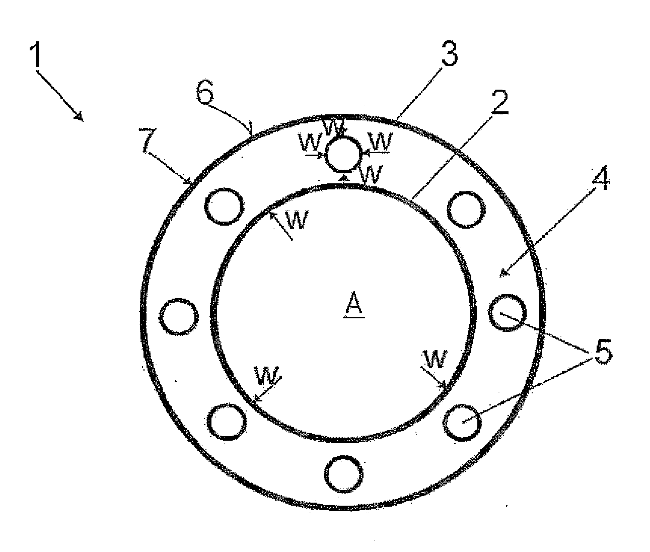
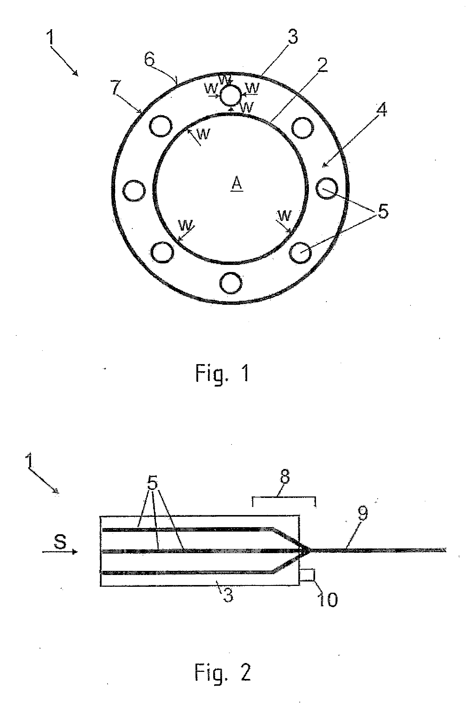
[0030]Turning now to the drawing, and in particular to FIG. 1, there is shown an exhaust system according to the present invention, generally designated by reference numeral 1. The exhaust system 1 includes an internal exhaust pipe 2 and a heat accumulator housing 3 in surrounding relationship to the exhaust pipe 2. Exhaust gas A flows in the exhaust pipe 2 and carries off h...


PUM


Abstract

An exhaust system for a combustion engine includes an exhaust pipe, and a heat accumulator housing in surrounding relationship to the exhaust pipe. Arranged in the heat accumulator housing are heat pipes to provide a heat transport of heat energy contained in exhaust gas. Heat energy thus withdrawn from the exhaust gas can be carried off via the heat pipes in the heat accumulator housing.

Description

CROSS-REFERENCES TO RELATED APPLICATIONS[0001]This application claims the priority of German Patent Application, Serial No. 10 2011 103 109.3, filed May 25, 2011, pursuant to 35 U.S.C. 119(a)-(d), the content of which is incorporated herein by reference in its entirety as if fully set forth herein.BACKGROUND OF THE INVENTION[0002]The present invention relates to an exhaust system for a combustion engine.[0003]The following discussion of related art is provided to assist the reader in understanding the advantages of the invention, and is not to be construed as an admission that this related art is prior art to this invention.[0004]Combustion engines, e.g. Otto engines or Diesel engines, consume fuels for operation. As oil reserves are limited, it is desired to maximize performance of a combustion engine and thus exploitation of energy contained in the fuel. Due to the Carnot process, the efficiency of a combustion engine for converting energy contained in the fuel into mechanical ene...

Claims


Application Information

Patent Timeline
Patent Type & Authority Applications(United States)
IPC IPC(8): F01N5/02F01N13/08
CPCY02T10/16F01N5/02F01N2470/24Y02E60/142F28D15/02F28D20/003F28D2020/0013F28D7/106Y02E60/14Y02T10/12
Inventor ANDRES, THORSTENDUPMEIER, TOBIASREUL, BENJAMIN
Owner BENTELER AUTOMOBILTECHNIK GMBH
Why Eureka
Try Eureka