Method for vacuum concentration

a vacuum concentration and concentrator technology, applied in the direction of centrifuges, evaporator regulation/control, instruments, etc., can solve the problems of sample overheating, sample not being dried for a long time, and considerable portions of residual liquid remain in the sample, etc., to achieve convenient suction, improve vacuum concentration efficiency, and monitor sample temperature accurately

Active Publication Date: 2012-12-06
EPPENDORF SE
View PDF17 Cites 4 Cited by
  • Summary
  • Abstract
  • Description
  • Claims
  • Application Information

AI Technical Summary

Benefits of technology

[0010]During the vacuum concentration, the pressure in the vacuum chamber is determined by the mass fluxes of the pumped off gases and / or vapours, of the air possibly flowing in as a result of leakages and the liquid vaporizing from the samples. At the end point of the drying, the last-mentioned effect is eliminated, as sample liquid is no longer vaporized. This time point may be established by monitoring the pressure inside the vacuum chamber. The invention is based on the fact that it detects the end point of the vacuum concentration by means of the detected pressure in the vacuum chamber and the vacuum concentration is terminated when the end point is determined. As a result, it is possible to carry out the vacuum concentration completely automatically. Prior knowledge of the material composition and / or the material data of the liquid to be vaporized and / or the solvent to be vaporized is not required. Thermal damage to the samples by overheating of the completely dried samples is avoided. Moreover, the duration of the vacuum concentration is shortened. The efficiency of the vacuum concentration is improved. Technically, the invention may additionally be easily implemented, as in principle it only requires the installation of a pressure sensor and a correspondingly designed control and evaluating device. The control and evaluating device may, in particular, be correspondingly configured hardware or a software-controlled data processing device.
[0012]According to a further embodiment, a vacuum pump with a relatively low delivery rate is applied to the vacuum chamber, which only gradually lowers the pressure in the vacuum chamber until the end point is reached, so that when the end point is reached, as a result of the absence of the release of vaporized sample components, the pressure in the vacuum chamber drops rapidly and the reaching of the end point is detected using the rapid pressure drop. The rapid pressure reduction may be particularly easily determined. This method allows the end point to be particularly reliably determined.
[0022]As the temperature sensor is arranged in a suction tube opening into the vacuum chamber and connected to the vacuum pump, the temperature sensor comes into intimate contact with the released vapours. The suction tube screens the temperature sensor from the surrounding regions of the vacuum chamber, so that it is avoided that the measurement is effected by heat exchange of the temperature sensor with the walls of the vacuum chamber. As a result, a more accurate monitoring and / or regulation of the temperature of the sample is permitted and the efficiency of the vacuum concentration is improved.

Problems solved by technology

However, there is the risk that the samples have not been dried for long enough, so that considerable portions of residual liquid remain in the samples.
Subsequent heating of samples which are already completely dried may lead to overheating of the samples.
In this connection, it is disadvantageous that an indication of the liquid and / or the solvent is required and the data have to be present for the relevant solvent.

Method used


Image

  • Method for vacuum concentration
  • Method for vacuum concentration
  • Method for vacuum concentration

Examples


Embodiment Construction

[0033]While this invention may be embodied in many different forms, there are described in detail herein a specific preferred embodiment of the invention. This description is an exemplification of the principles of the invention and is not intended to limit the invention to the particular embodiment illustrated

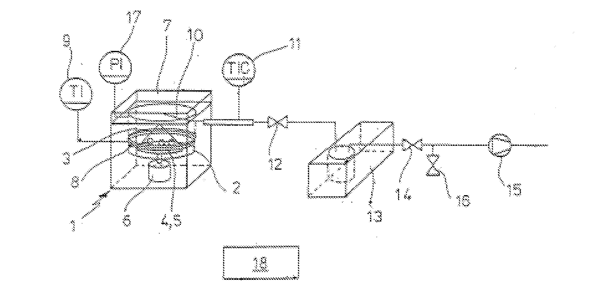
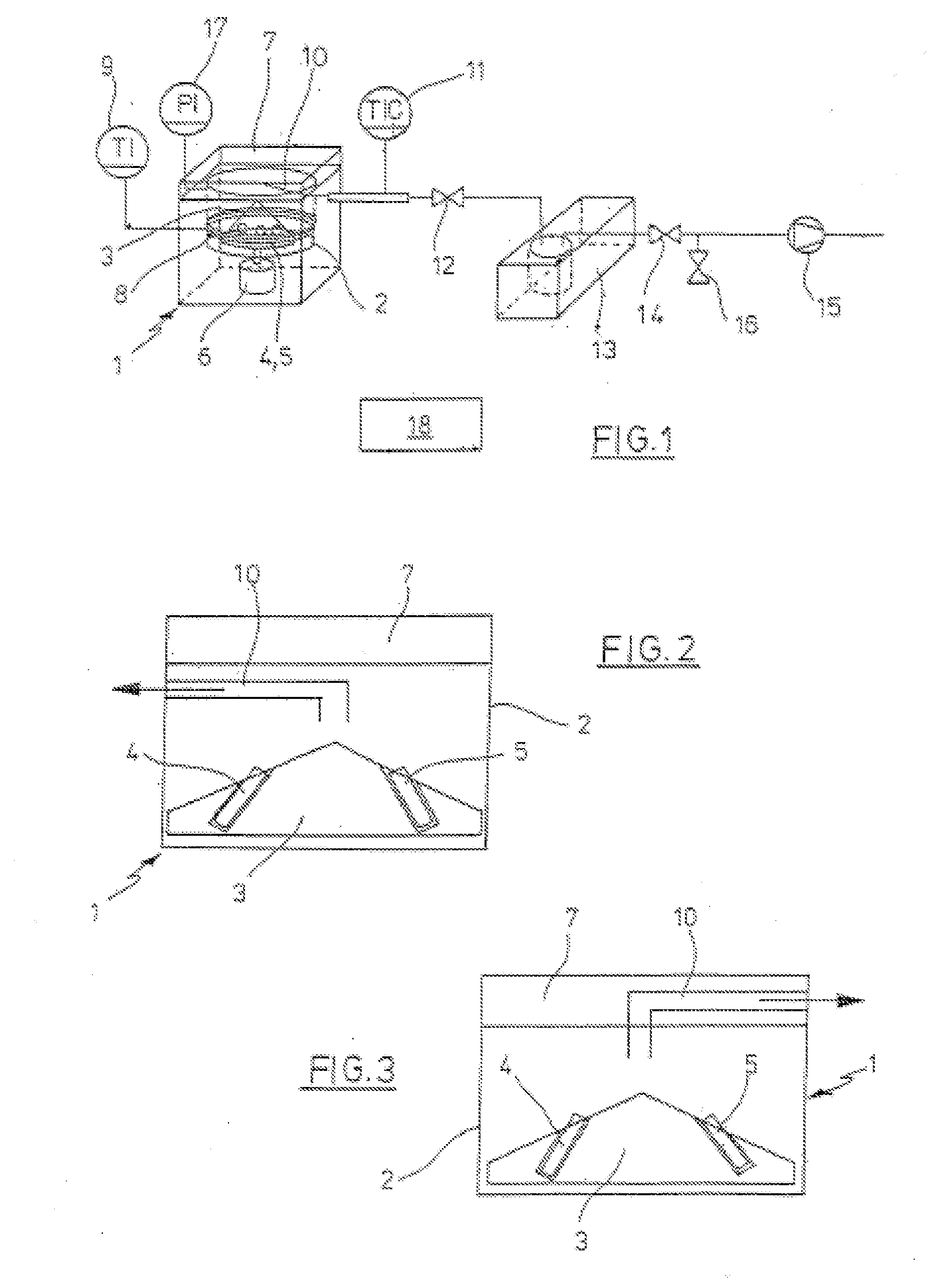
[0034]According to FIG. 1, the vacuum concentrator comprises a housing 1, with a vacuum chamber 2, in which a centrifuge rotor 3 is arranged with a plurality of receivers 4 for sample vessels 5. Outside the vacuum chamber 2 a drive unit 6 (for example with an electrical drive motor) for driving the centrifuge rotor 3 is arranged in the housing 1.

[0035]The vacuum chamber 2 is sealed at the top by a closure in the form of a sealing cover 7, which may be folded back.

[0036]A heating device 8 is associated with the vacuum chamber 2, and which comprises electrical resistance wires, which surround the vacuum chamber 2. A temperature sensor 9 for measuring the temperature of the heati...


PUM


Abstract

Vacuum concentrator, comprising a vacuum chamber with a closure which may be sealed in an airtight manner, a centrifuge rotor arranged in the vacuum chamber with at least one receiver for at least one vessel for samples to be dried, a drive motor arranged outside the vacuum chamber for driving the centrifuge rotor, a vacuum pump connected to the vacuum chamber, a tempering device associated with the vacuum chamber for tempering the at least one sample in the vacuum chamber, a pressure sensor associated with the vacuum chamber for detecting the pressure inside the vacuum chamber and an electrical control and evaluating device which is connected to the drive motor, the vacuum pump, the tempering device and the pressure sensor, for detecting the end point of the vacuum concentration by means of the pressures detected by the pressure sensor in the vacuum chamber and terminating the vacuum concentration when the end point is determined.

Description

CROSS-REFERENCE TO RELATED APPLICATIONS[0001]This application is a divisional of application Ser. No. 11 / 927,949, filed Oct. 30, 2007, the entire contents of which is hereby incorporated by reference.STATEMENT REGARDING FEDERALLY SPONSORED RESEARCH[0002]Not applicable.BACKGROUND OF THE INVENTION[0003]The invention relates to a vacuum concentrator and to a method for vacuum concentration.[0004]Vacuum concentration is used in the chemical industry and in the laboratory, in particular within the scope of solid-liquid extraction and for drying wet, thermally unstable samples. In this connection, the fact that the boiling point of a liquid is reduced in the vacuum is utilized. As a result, the boiling liquid in the vacuum may escape from a wet sample at relatively low temperatures. To this end, the samples are arranged in a vacuum chamber which is evacuated by means of a vacuum pump. In order to prevent an uncontrolled release of liquid from the samples, said samples are arranged in the ...

Claims


Application Information

Patent Timeline
Patent Type & Authority Applications(United States)
IPC IPC(8): F26B5/08
CPCB01D1/0082B04B13/00G01N2001/4027G01N1/4022B04B15/08
Inventor RAMHOLD, FRANKVAN DEN BERGHE, KLAASGRIMM, BERT-OLAFGOEMANN, WOLFGANGHESS, REBECCAFRANCKE, FELIX
Owner EPPENDORF SE
Why Eureka
Try Eureka