Direct-action superconducting synchronous generator for a wind turbine

a superconducting, direct-action technology, applied in the direction of electric generator control, machines/engines, mechanical equipment, etc., can solve the problems of reducing the efficiency of wind energy conversion into mechanical energy, poor efficiency of electric generators and electric machines in general, and needing intensive and scheduled maintenan

Inactive Publication Date: 2012-12-06
FUNDACION TECNALIA RES & INNOVATION
View PDF0 Cites 26 Cited by
  • Summary
  • Abstract
  • Description
  • Claims
  • Application Information

AI Technical Summary

Problems solved by technology

Electric generators and electric machines in general, exhibit poor efficiency when driven at very low speed.
Gearboxes reduce the efficiency of the conversion of wind energy into mechanical energy used for driving the electric generator rotor and are moreover rather expensive, need intensive and scheduled maintenance and are open to wear-out and thereto related failures.
Direct-drive generators based on conventional electric machines technologies do not comprise gearboxes and thus lack the disadvantages thereof, but are intrinsically heavier and larger.
This is remarkably the case of slow electric generators for wind turbines whose nacelles, equipped with such generators, are more difficult to lift, to place and to balance on towers so that they are rather unsuitable for high-power producing generators as wind turbines.
However, this class of superconductors is very expensive as BSCCO has silver matrix and YBCO is very difficult to manufacture in long pieces such as those required for coils, and the production requires time-consuming processes and complicated technologies.
As a consequence, electric machines implementing HTS are too expensive.
Plants for liquifying helium are also very expensive.
Moreover, the lower the temperature, the more unstable is the cryogenic system.
These are serious disadvantages of LTS machines.
On the other hand, to carry high currents at these temperatures, existing wires based on magnesium diboride cannot take very high magnetic fields, usually well below 2T.
The “cold rotor” design as the one disclosed in WO-A 2007 / 033858 is not suitable for salient poles rotor, because the cryostat external jackets above the poles would require extra space, thus making the air-gap longer and having a negative effect in the magnetic field distribution.
This feature would reduce the efficiency of the magnetic circuit.
As He is a very expensive element, several closed-cycle systems have been developed to recover these expensive gas, and, even, liquefied it again.
All of them need a continuous re-filling of the cryostat or expensive recovery systems based on liquid plants.

Method used


Image

  • Direct-action superconducting synchronous generator for a wind turbine
  • Direct-action superconducting synchronous generator for a wind turbine
  • Direct-action superconducting synchronous generator for a wind turbine

Examples


Embodiment Construction

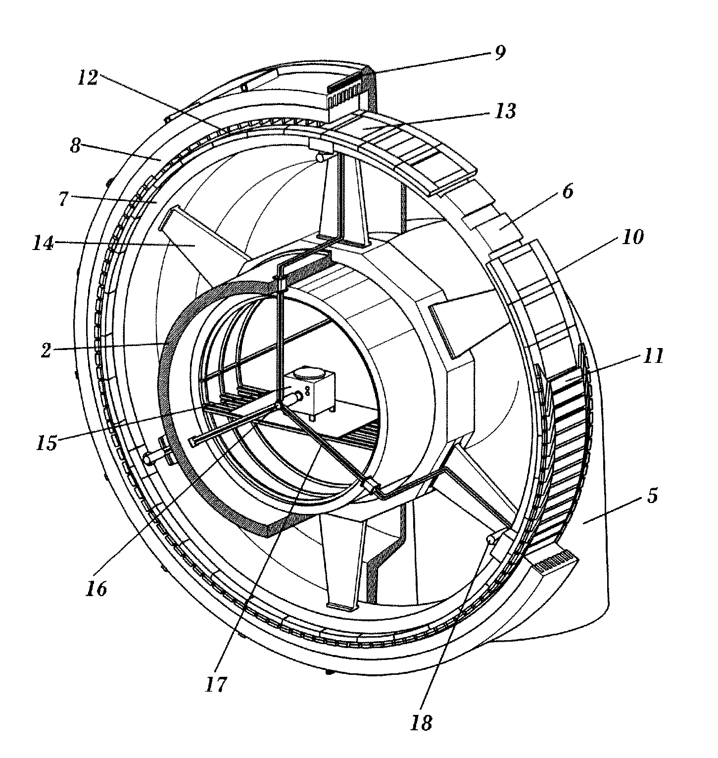
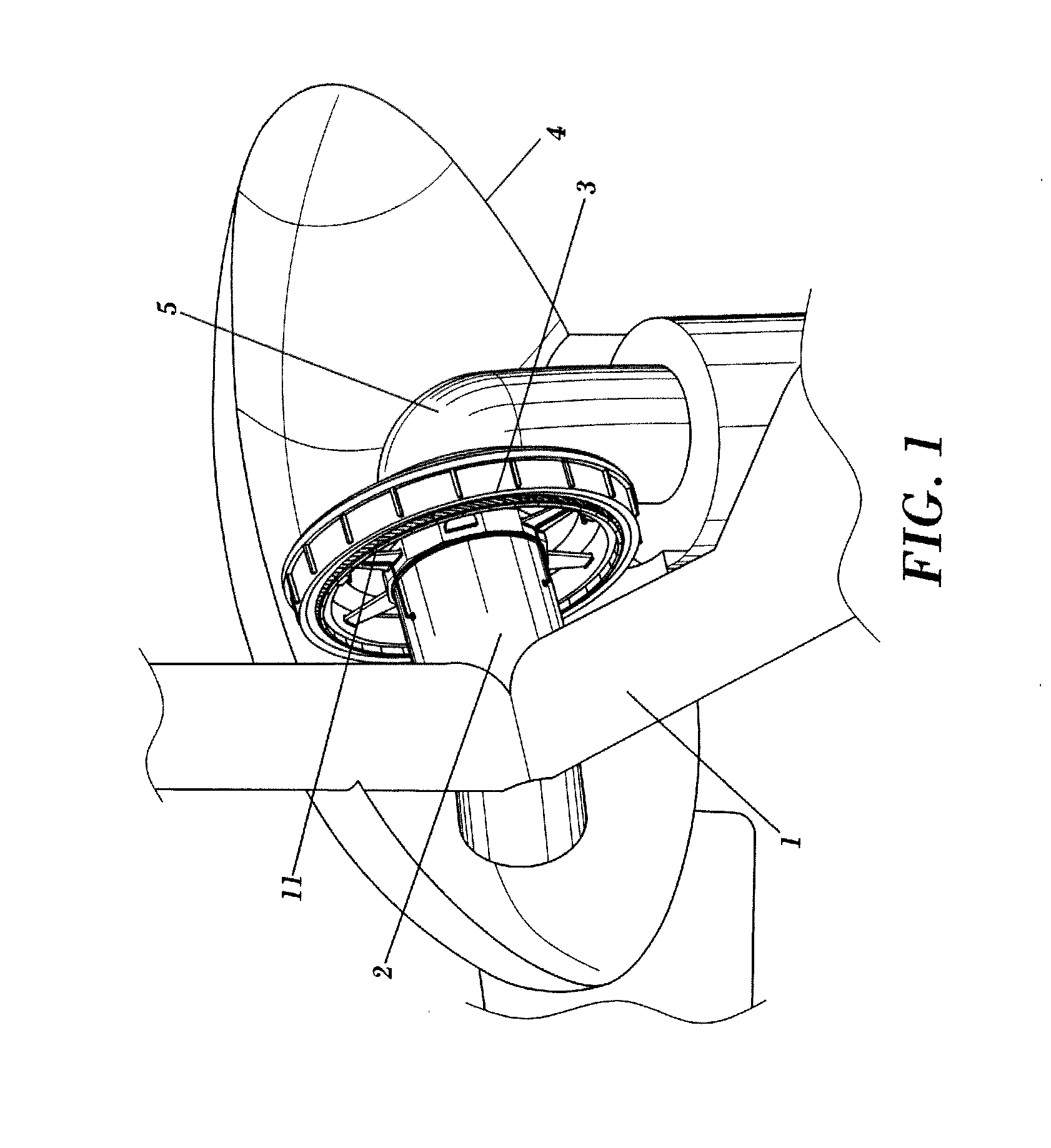
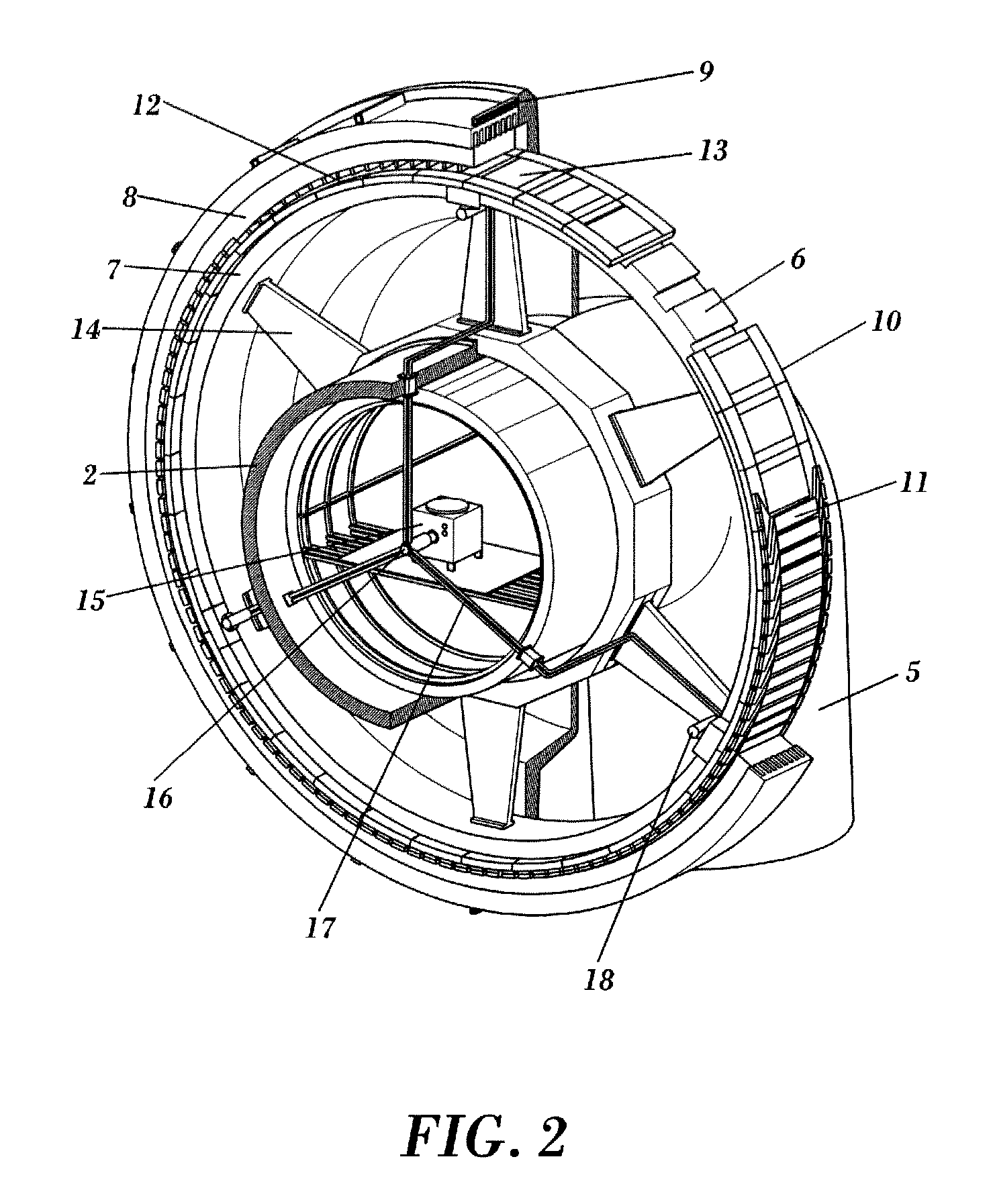
[0014]The present invention is intended to overcome the aforementioned drawbacks of the prior art by providing a direct-drive electric generator as claimed in claim 1.

[0015]The warm poles rotor, i.e. the “warm rotor” holds a cryostat of suitable geometry. We will refer to the cryostat of aforementioned geometry as the “Hamster wheel” type. Inside the cryostat, the superconducting field windings preferably based on magnesium diboride wire, are kept at the proper cryogenic temperature. This design has a series of advantages with respect to conventional “cold rotor” designs:[0016]rotor materials are conventional;[0017]the outer surface of the cryostat reduced so that the radiation thermal flux entering the cryostat is minimized;[0018]volume and mass within are reduced so that the time for respectively creating the vacuum and cooling the coils is reduced;[0019]the cryostat can be made modular; each coil comes with its own cryostat element case so that once all elements are in place on t...


PUM


Abstract

The invention refers to a direct drive electric generator for a wind turbine provided with rotor salient poles and a ladder-like cryostat for housing superconductive coils and keeping them at a cryogenic temperature while the interior of the cryostat is kept free of coolant.
The invention achieves optimal thermal insulation of the coils without the need of a continuous re-filling of the cryostat and ensuring a good distribution of the magnetic field avoiding the use of expensive materials.

Description

TECHNICAL FIELD OF THE INVENTION[0001]The present invention lies within the technical field of electric generators that comprise a rotor and a stator for the production of electric power and, particularly, to low-speed, direct-drive synchronous generators comprising superconducting field windings for use in wind turbines.BACKGROUND OF THE INVENTION[0002]Wind turbines are nowadays considered as a “green” source of energy and, in fact, belong to one of the most developed renewable technologies. Most wind turbines are horizontal-axis wind turbines having a rotor provided with three blades connected to a main rotor shaft and an electrical generator mounted within a nacelle at the top of a tower. Many conventional types of wind turbines comprise a gearbox that converts the relatively slow rotation of the wind turbine rotor into a faster rotation to drive the electric generator rotor. Electric generators and electric machines in general, exhibit poor efficiency when driven at very low spe...

Claims


Application Information

Patent Timeline
Patent Type & Authority Applications(United States)
IPC IPC(8): F03D9/00
CPCF03D9/002F05B2220/70642F05B2260/20H02K2213/12H02K55/04Y02E10/725Y02E40/625H02K7/1838F03D9/25F03D80/60Y02E10/72Y02E40/60
Inventor SARMIENTO MUNOZ, GUSTAVOMERINO AZCARRAGA, JOSE MARIAGARCIA-TEJEDOR PEREZ, JAVIERIBANEZ ERENO, PEDROAPINANIZ APINANIZ, SUSANA
Owner FUNDACION TECNALIA RES & INNOVATION
Why Eureka
Try Eureka