Laser ignition system

a technology of laser ignition system and laser pulse, which is applied in the direction of lasers, mechanical equipment, machines/engines, etc., can solve the problems of too large time lag between these laser pulses, and one highly energetic laser pulse available, so as to improve the mechanical robustness of the system

Inactive Publication Date: 2012-12-13
ROBERT BOSCH GMBH
View PDF13 Cites 16 Cited by
  • Summary
  • Abstract
  • Description
  • Claims
  • Application Information

AI Technical Summary

Benefits of technology

[0004]Laser devices according to the present invention and laser ignition systems according to the present invention having the features described herein have the advantage over the related art that multiple highly energetic laser pulses may be provided at a small but defined time lag, e.g., in the range of one hundred picoseconds or one nanosecond. In this way, it is possible to apply multiple laser pulses during one power stroke of an internal combustion engine, and to thus improve the ignition behavior of the internal combustion engine.
[0010]In an alternative or additional advantageous refinement of the exemplary embodiments and / or exemplary methods of the present invention, it is provided that the laser device includes a highly reflective mirror. With the aid of this mirror, it is possible in a low-loss manner to deflect the laser pulses, which initially propagate into different directions, in particular in such a way that they propagate coaxially to one another.
[0013]A configuration of this type has the advantage that the laser pulse passes through the laser amplifier or the second laser-active solid for a second time, this time in the opposite direction, and experiences an additional amplification in the process.
[0016]In an advantageous refinement of the present invention, measures are to be provided to ensure that a bleaching out of the optical Q-switch takes place, when the laser device is acted on by the pumped light, before a population inversion, which corresponds to a laser threshold, occurs within the second laser-active solid. In this way, it is avoided that a laser mode starts oscillating on its own within the amplifier.
[0018]A monolithic embodiment of the laser oscillator and / or of the laser amplifier improves the mechanical robustness of the system. For this purpose, one mirror or all mirrors may be applied as a reflective coating on the first and / or the second laser-active solid(s) and / or on the optical Q-switch. Additionally or alternatively, it is possible to monolithically connect the first laser-active solid to the optical Q-switch, in particular by optical contacting, bonding and / or sintering.

Problems solved by technology

This laser device has the disadvantage that only one highly energetic laser pulse is made available after the bleaching out of the passive Q-switch.
Although in principle, another laser pulse may be emitted through the output mirror after new pumping of the laser-active solid and after new bleaching out of the passive Q-switch, the time lag between these laser pulses is, however, in many cases too large to have a favorable effect on the function of an ignition system during a power stroke of the internal combustion engine.

Method used


Image

  • Laser ignition system
  • Laser ignition system
  • Laser ignition system

Examples


Embodiment Construction

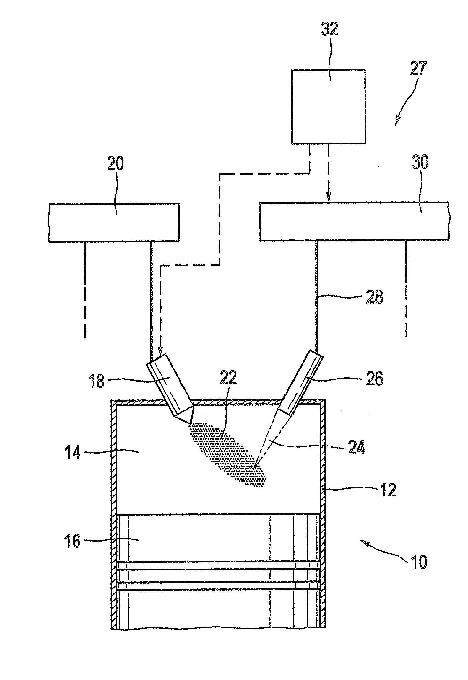
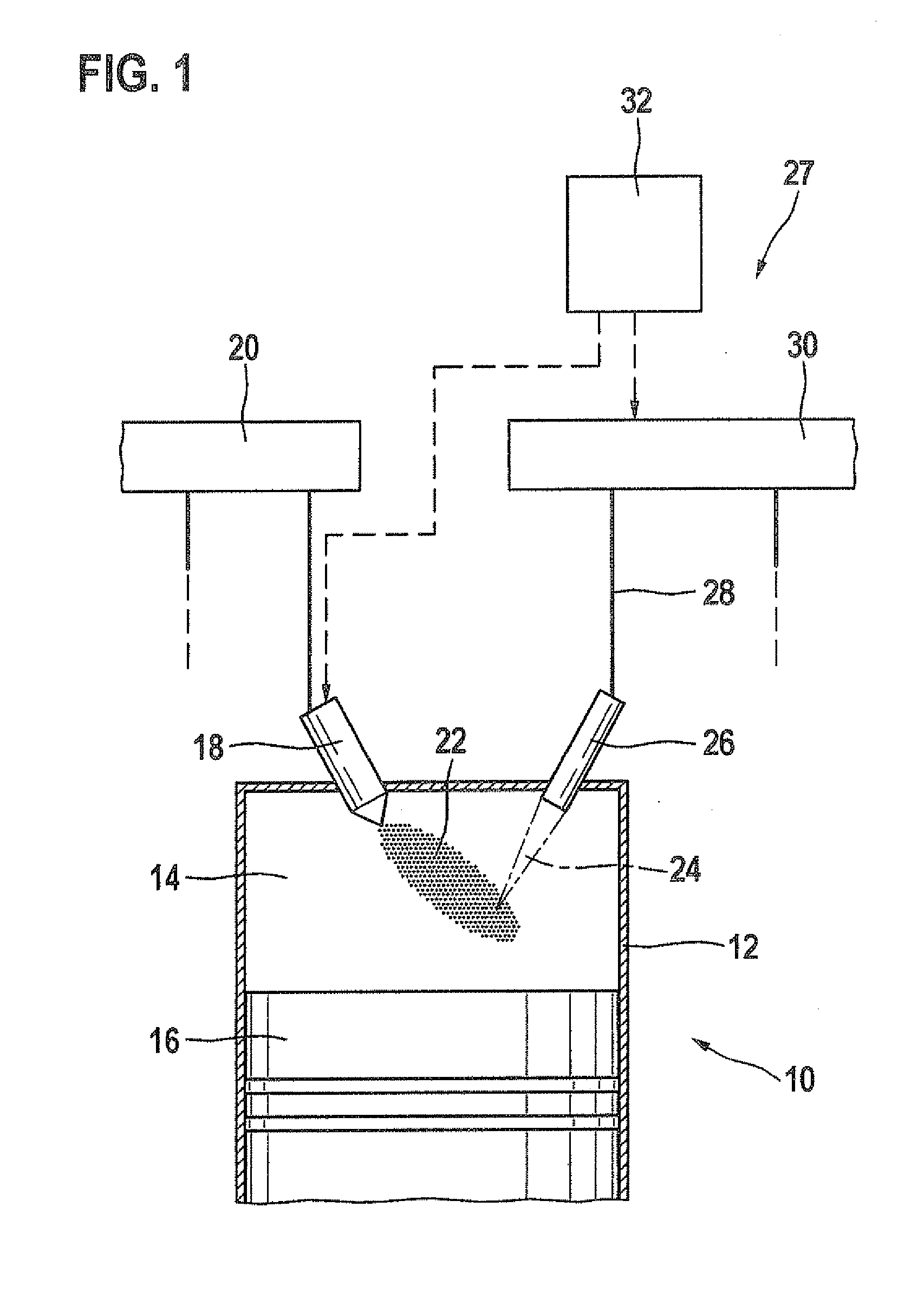
[0023]In FIG. 1, an internal combustion engine is identified as a whole by reference numeral 10. It is used for driving a motor vehicle (not illustrated) or as a stationary engine. Internal combustion engine 10 includes multiple cylinders, only one of which is labeled with reference numeral 12 in FIG. 1. A combustion chamber 14 of cylinder 12 is delimited by a piston 16. Fuel reaches combustion chamber 14 directly through an injector 18, which is connected to a fuel pressure accumulator 20.

[0024]Fuel 22 injected into combustion chamber 14 is ignited with the aid of at least one laser pulse 24 which is emitted into combustion chamber 14 by an ignition device 27 which includes a laser device 26. For this purpose, laser device 26 is supplied, via fiber optic device 28, with a pumped light provided by a pumped light source 30. Pumped light source 30 is controlled by a control and regulating device 32, which also activates injector 18.

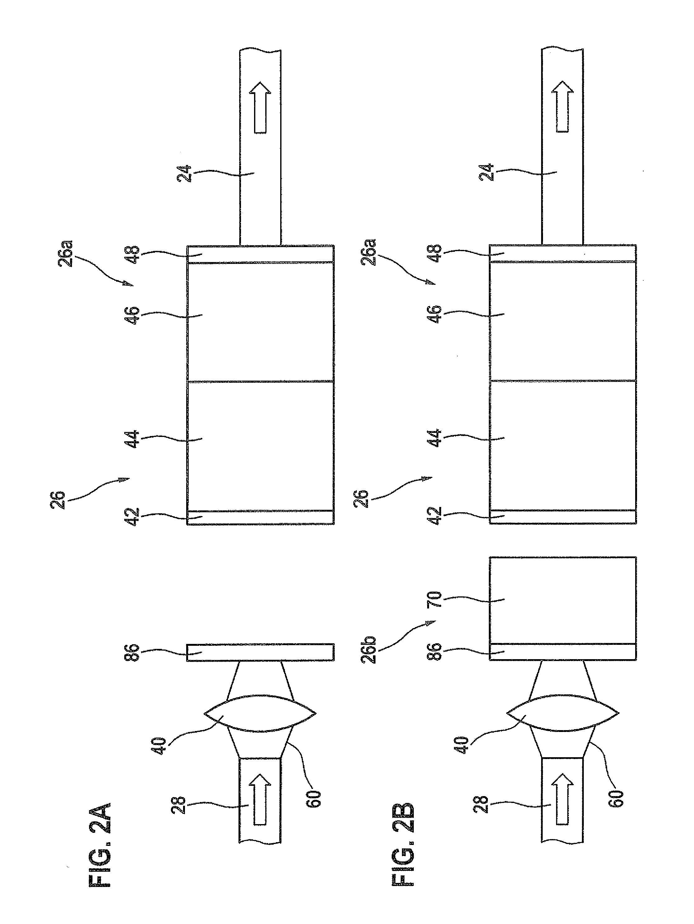
[0025]A first specific embodiment of a laser device 2...


PUM


Abstract

A laser device for a laser ignition system for an internal combustion engine, in particular of a motor vehicle or a stationary engine, including a laser oscillator, the laser oscillator having a first laser-active solid, an optical Q-switch, and an output mirror which is partially reflective for a light to be generated by the laser device, in which the laser oscillator has another mirror which is partially reflective for the light to be generated by the laser device.

Description

FIELD OF THE INVENTION[0001]The present invention is directed to a laser device. The present invention also relates to a corresponding laser ignition device and a method for operating a laser ignition device.BACKGROUND INFORMATION[0002]An ignition device, which includes a laser device having a laser-active solid, for an internal combustion engine is discussed in WO 2006 / 125685 A1. The laser device further includes an input mirror, an output mirror, and a passive Q-switch. Here, the input mirror is highly reflective for the wavelength of the laser light, and the output mirror is partially reflective for the wavelength of the laser light so that the laser-active solid emits a highly energetic laser pulse through the output mirror after optical excitation of the laser-active solid and after the bleaching out of the passive Q-switch. Subsequently, the emitted laser pulse is available for igniting a fuel / air mixture.[0003]This laser device has the disadvantage that only one highly energe...

Claims


Application Information

Patent Timeline
Patent Type & Authority Applications(United States)
IPC IPC(8): F02P23/00
CPCF02P23/04H01S3/0621H01S3/0627H01S3/07H01S3/082H01S3/2333H01S3/09415H01S3/113H01S3/1611H01S3/1643H01S3/094076
Inventor RIDDERBUSCH, HEIKO
Owner ROBERT BOSCH GMBH
Why Eureka
Try Eureka