Vacuum degreasing and cleaning apparatus and vacuum degreasing and cleaning method

a vacuum cleaner and vacuum cleaner technology, applied in the direction of cleaning processes and utensils, cleaning using liquids, chemistry apparatus and processes, etc., can solve the problems of difficult uniform cleaning, inability to exclude adherents, complex loading process etc., to achieve enhanced cleaning effect of objects to be cleaned, shorten cleaning time, and enhance the effect of removal of contamination

Inactive Publication Date: 2012-12-13
NACHI-FUJIKOSHI
View PDF6 Cites 2 Cited by
  • Summary
  • Abstract
  • Description
  • Claims
  • Application Information

AI Technical Summary

Benefits of technology

[0032]As described above, in the present invention, by the vacuum degreasing and cleaning apparatus having a cleaning chamber having an injector and a sprayer that eject a solvent to an object to be cleaned, a plurality of storage tanks that store the solvent, a distiller that distills the solvent in the storage tank, and a replenisher tank that stores the solvent distilled by the distiller, wherein a heating means is included in the inside of the sprayer in a nesting way, the solvent which is sprayed from the sprayer is gasified (vaporized) in the cleaning chamber, and therefore, the solvent vapor (vaporized solvent) can be efficiently introduced into the cleaning chamber (introduction efficiency becomes high). As a result, the solvent spreads to, for example, every corner of surfaces to be cleaned of the insides of downward blind holes which the solvent hardly reaches by the cleaning methods of sprinkling, injection, immersing and the like, and every corner of the surfaces to be cleaned can be ...

Problems solved by technology

However, the cleaning apparatus disclosed in JP-A-2005-342639 has the problem that even though the cleaning apparatus is of the type which performs cleaning with a plurality of cleaning nozzles, in the case of objects to be cleaned in a complicated shape, uniform cleaning is difficult unless a loading method according to a certain rule is adopted.
More specifically, in order to clean the objects to be cleaned uniformly, the loading method thereof is naturally determined in accordance with the shapes and the sizes of the objects to be cleaned, and therefore, there arises the problem that the loading process of the objects to be cleaned is complicated.
Further, the cleaning apparatus disclosed in Japanese Patent No. 3759439 has the problem that when the solvent is discharged outside the chamber from the cleaning chamber after immersing and cleaning with the solvent, particulate adherents such as cut dust and abrasive powder removed from the surfaces of the objects to be cl...

Method used


Image

  • Vacuum degreasing and cleaning apparatus and vacuum degreasing and cleaning method
  • Vacuum degreasing and cleaning apparatus and vacuum degreasing and cleaning method
  • Vacuum degreasing and cleaning apparatus and vacuum degreasing and cleaning method

Examples


example

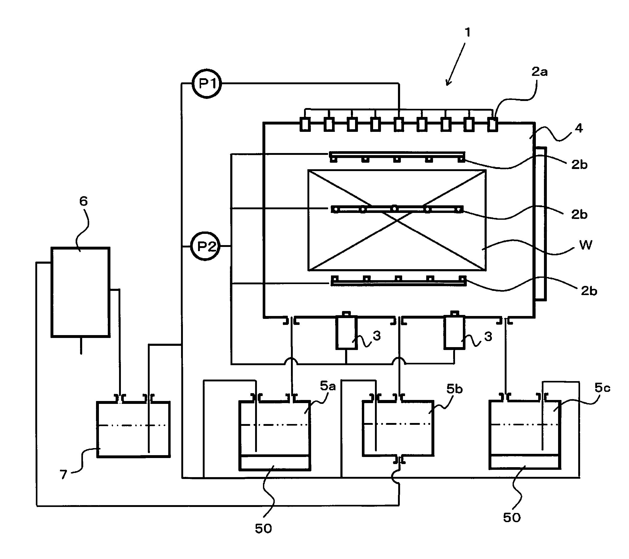
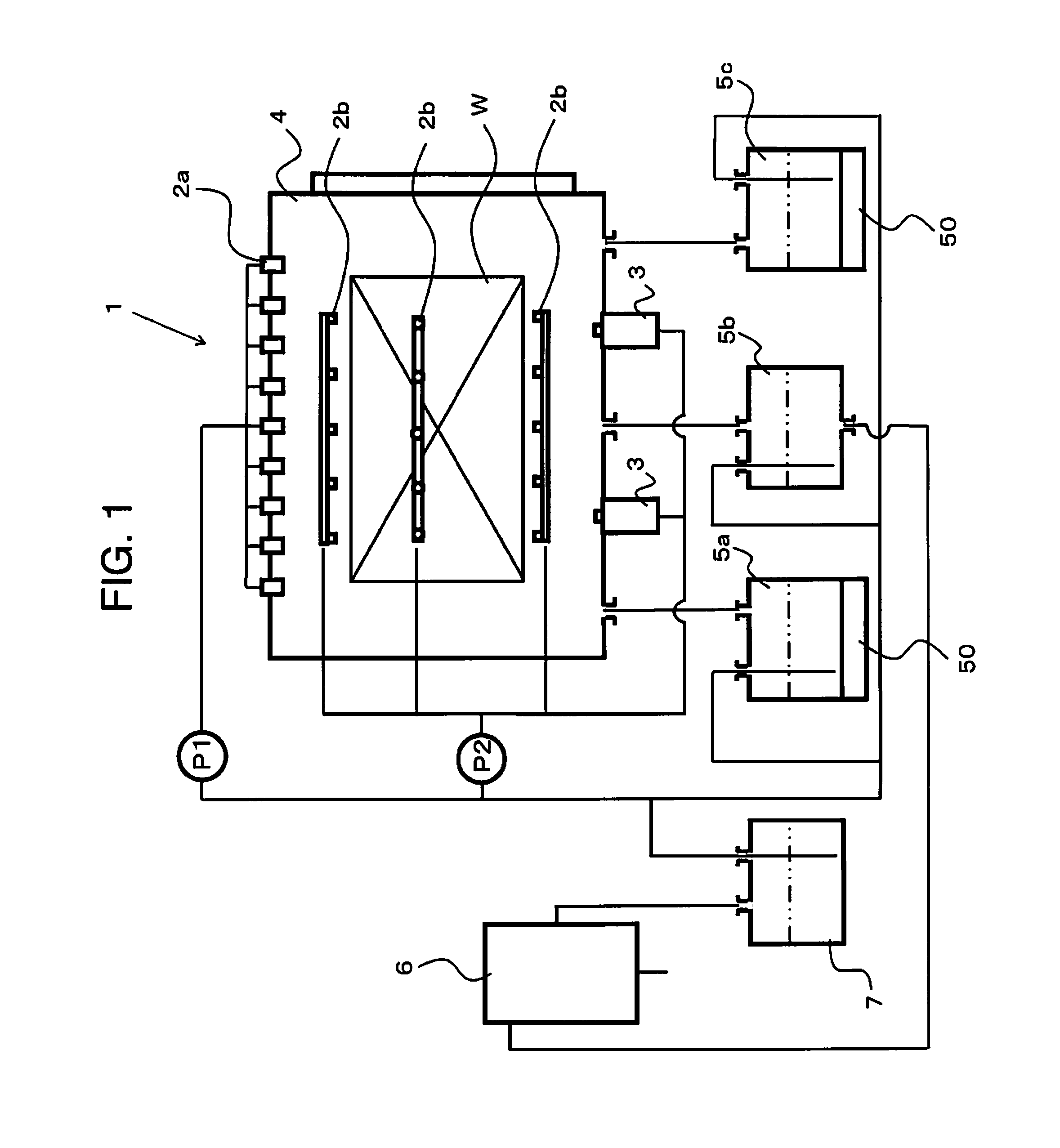
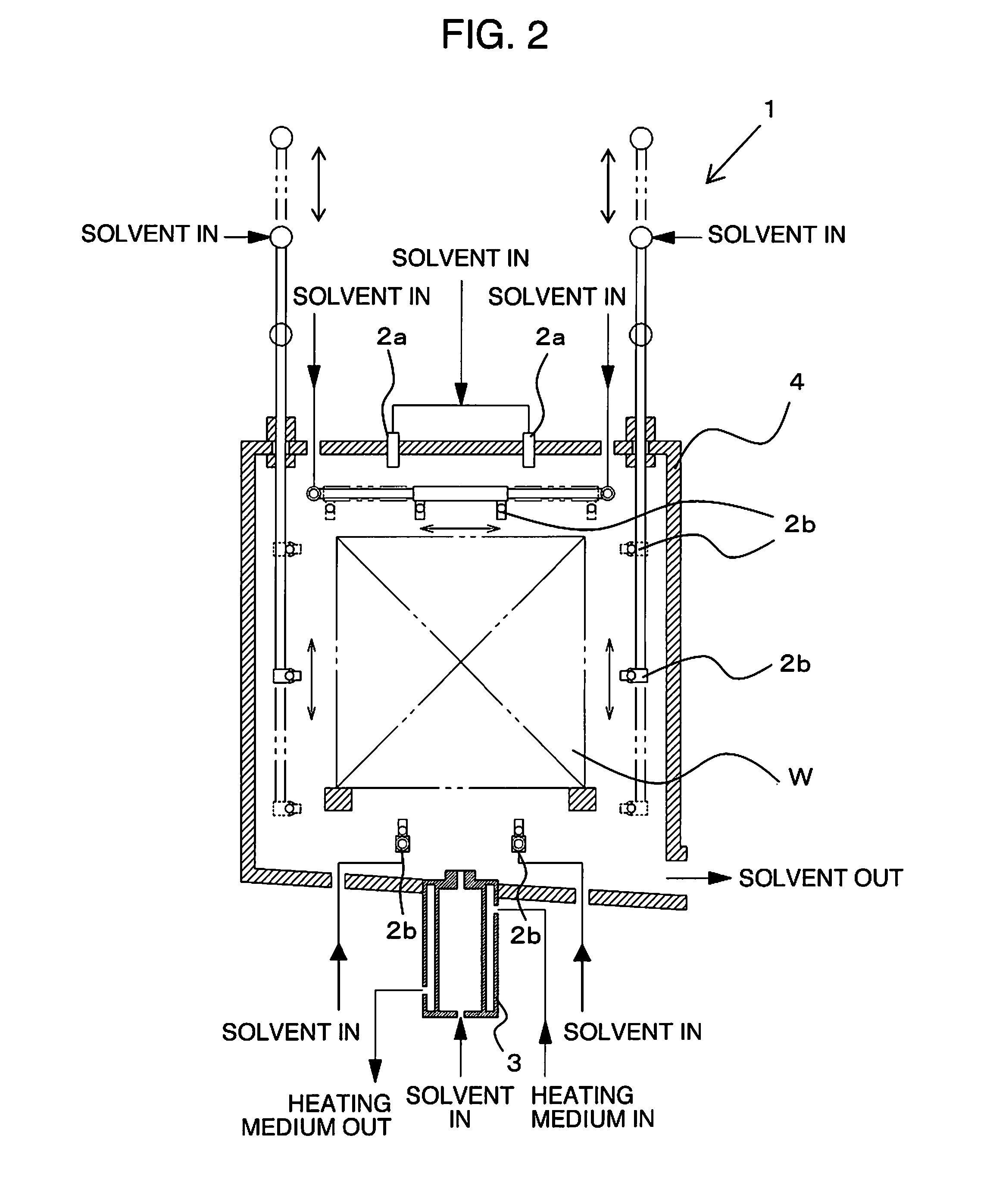
[0067]Since a cleaning test for four kinds of specimens (the objects W to be cleaned) which differ in shapes and loading modes from one another was performed by using the vacuum degreasing and cleaning apparatus 1 of FIG. 1 which is shown in the embodiment of the present invention, the test result will be described by using FIG. 11 to FIG. 14. FIG. 11 is a schematic view of the work shapes and the loading mode of a specimen A which was used in the cleaning test of the present example. FIG. 12 is a schematic view of the work shapes and the loading mode of a specimen B which was used in the same test. FIG. 13 is a schematic view of the work shapes and the loading mode of a specimen C which was used in the same test. FIG. 14 is a schematic view of the work shapes and the loading mode of a specimen D which was used in the same test. In regard to the cleaning result, degreasing, drying, and presence / absence of remaining particulate contaminants were visually evaluated.

[0068]The specimens...


PUM


Abstract

There is provided a vacuum degreasing and cleaning apparatus, including a cleaning chamber having an injector and a sprayer that eject a solvent to an object to be cleaned, a plurality of storage tanks that store the solvent, a distiller that distills the solvent in the storage tank, and a replenisher tank that stores the solvent distilled by the distiller, wherein a heating means is provided in the inside of the sprayer in a nesting way. There is also provided a vacuum degreasing and cleaning method using the aforementioned vacuum degreasing and cleaning apparatus, wherein the solvent is pressurized and supplied to the inside of the sprayer, heated to a temperature not lower than a saturation temperature in the cleaning chamber under a reduced pressure, and thereafter sprayed in the cleaning chamber under the reduced pressure.

Description

BACKGROUND OF THE INVENTION[0001]1. Field of the Invention[0002]The present invention relates to a vacuum degreasing and cleaning apparatus which degreases and cleans mechanical parts and the like under a vacuum / reduced pressure, and a vacuum degreasing and cleaning method thereof.[0003]2. Description of Related Art[0004]Since oils and fats such as cutting oils and quenching oils and dusts adhere in the working processes to surfaces of metal parts for use in automobiles, construction machines, agricultural machines, the other industrial machines and the like, these adherents need to be removed before the parts are incorporated into products. In particular, when the adherents on the surfaces of parts are to be removed (degreased) by a solvent of hydrocarbon or the like, degreasing and cleaning are often performed under an atmosphere in which air is cut off, for example, under a vacuum / reduced pressure, in order to prevent the solvent from igniting.[0005]The cleaning method under a va...

Claims


Application Information

Patent Timeline
IPC IPC(8): B08B3/02B08B3/14
CPCB08B3/02B08B3/10B08B3/08
Inventor SAKAI, AKIRA
Owner NACHI-FUJIKOSHI
Why Eureka
Try Eureka