Branch pipe

a branch pipe and pipe structure technology, applied in the direction of couplings, heating types, lighting and heating apparatus, etc., can solve the problems of complex structure, high construction cost, and difficult construction work, and achieve the effect of easy coupling, preventing any interference of branch pipes during coupling, and easy coupling

Active Publication Date: 2012-12-13
CHOI YUK NAM
View PDF35 Cites 17 Cited by
  • Summary
  • Abstract
  • Description
  • Claims
  • Application Information

AI Technical Summary

Benefits of technology

[0020]As described above, the manifold type pipe structure according to the present invention is directed to easily coupling branch pipes in such a way that the branch pipes are easily coupled with limited rotation angles, not adapting a conventional thread coupling method for thereby preventing any interference from branch pipes during a coupling.
[0021]In addition, the manifold type pipe structure according to the present invention is directed to enhancing the compatibility of pipes in such a way to concurrently adapt a double type method of coupling a pipe at both ends in terms of pipes and a single type method coupling a pipe at one end of both ends.
[0022]In addition, the manifold type pipe structure according to the present invention is directed to enhancing the efficiency of work with the aid of a faster coupling in such a way to couple branch pipes in an airtight coupling method with only the rotations in an acute angle range when coupling, in series, branch pipes with limited rotation angles.
[0023]The manifold type pipe structure according to the present invention ensures good heat resistance performance, desired strength and impact and abrasion resistance performances since it is made from an engineering plastic as a principle material and makes it possible save a manufacture cost since the manifold type pipe structure is made in an extrusion molding method.

Problems solved by technology

However, the above mentioned conventional hot water distribution pipe is configured in such a way that the threads are formed on the outer surfaces of the inlet and outlet port and the distribution ports which helps an airtight communication with the water transfer pipe and the water return pipe and the heating pipe, and a plurality of nuts are coupled after a sealing member is engaged, so the structure is complicated, and a construction work is hard, and the construction costs a lot.

Method used


Image

  • Branch pipe
  • Branch pipe
  • Branch pipe

Examples


Embodiment Construction

[0043]The preferred embodiments of the present invention will be described with reference to the accompanying drawings.

[0044]It is noted that the same elements or parts shown in the drawing are given the same reference numerals, and in the following descriptions, the descriptions on the known functions or constructions will be omitted for simplification.

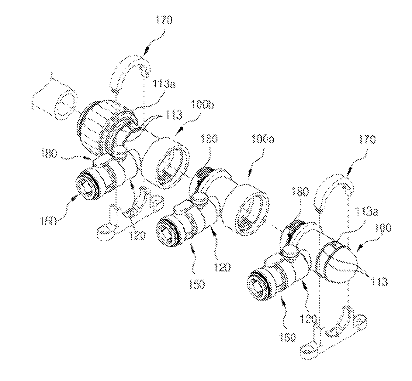
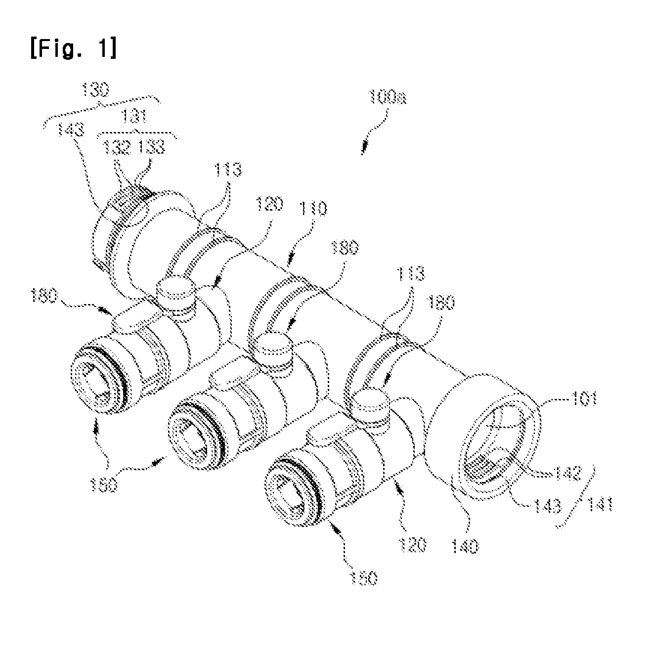
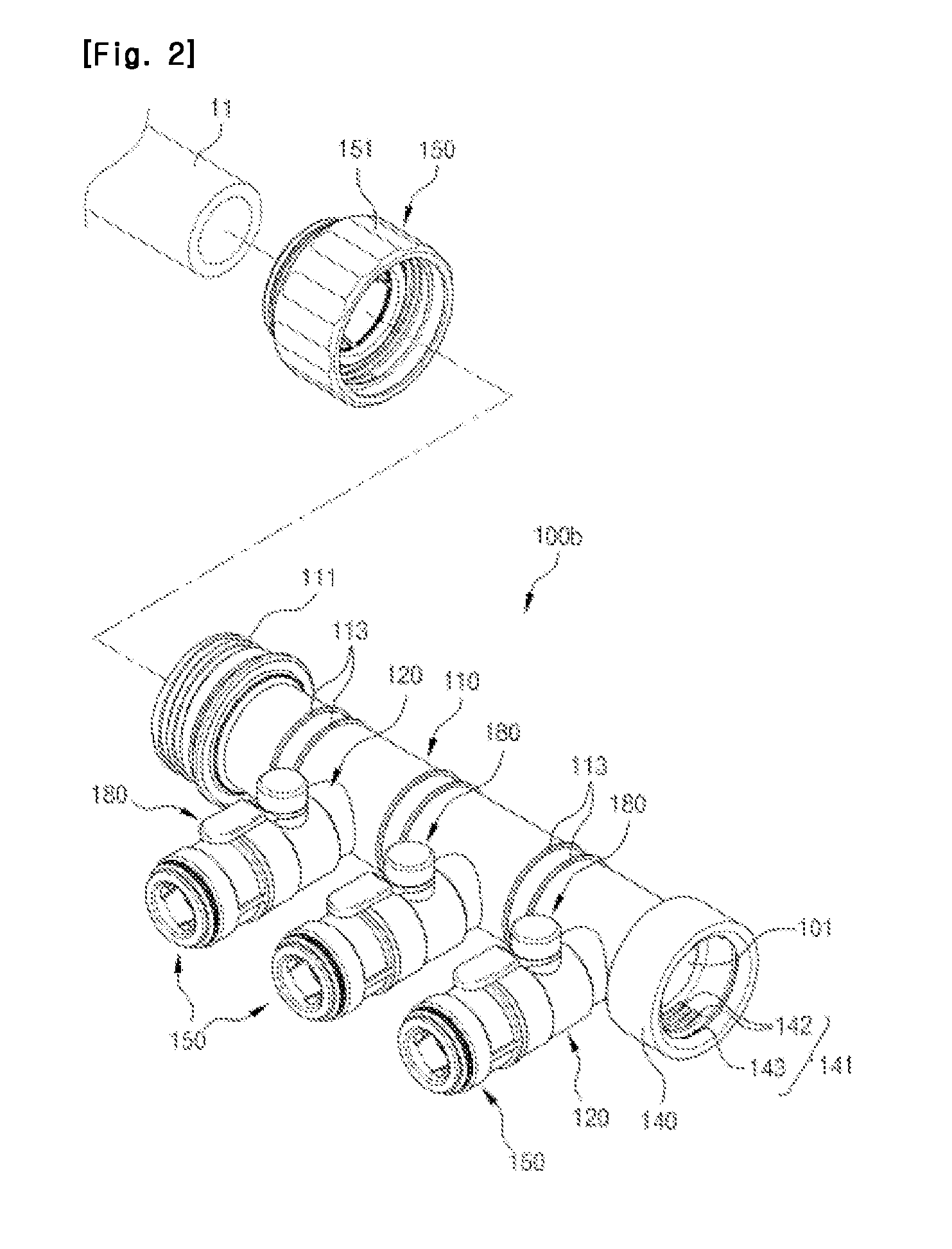
[0045]FIG. 1 is a perspective view illustrating a joint coupler of a manifold type pipe structure according to the present invention. FIG. 2 is a perspective view illustrating a pipe coupler of a manifold type pipe structure according to the present invention. FIG. 3 is a perspective view illustrating a finishing coupler of a manifold type pipe structure according to the present invention. FIG. 4 is a perspective view illustrating a pipe coupler of a manifold type pipe structure according to a first embodiment of the present invention. FIG. 5 is a perspective view illustrating a pipe coupler of a manifold type pipe structure accordin...


PUM


Abstract

The manifold type pipe structure according to the present invention is characterized in that at least branch pipe is formed at a pipe passage having a flow hole through which fluid flows, and an input valve is formed at an end portion of the pipe passage, and a joint coupler forming an output valve at the other end portion is prepared, and an output valve of a joint coupler of the other places is joint-connected with a limited rotation angle at an input valve of at least one joint coupler.

Description

TECHNICAL FIELD[0001]The present invention elates to a manifold type pipe structure, and in particular to a manifold type pipe structure which makes it possible to easily couple branch pipes with a limited rotation angle while ensuring airtight connections.BACKGROUND ART[0002]A hot water distribution pipe for a boiler is generally configured in such a way that an inlet and outlet port is formed at an end portion of a branch pipe body, and distribution ports are formed at an outer surface of it, and the inlet and outlet port communicates with a boiler body, and the distribution ports communicate with heating pipes connected to an indoor compartment. A threaded portion is formed at the inner surfaces and the outer surfaces of the inlet and outlet port and the distribution ports, respectively. A water transfer pipe or a water return pipe is connected to the inlet and outlet port, and a heating pipe communicates with the distribution ports.[0003]The above mentioned hot water distributio...

Claims


Application Information

Patent Timeline
Patent Type & Authority Applications(United States)
IPC IPC(8): F16K11/22F16L19/00
CPCF16L19/065F16L37/0925F16L37/2445F24D19/0097F16L41/021F16L41/03F24D3/1075F16L37/252Y10T137/87877F16L37/0927F16L3/1083F24D3/10F16L41/02F16L41/16
Inventor CHOI, YUK NAM
Owner CHOI YUK NAM
Why Eureka
Try Eureka