
Power transmission chain

a transmission chain and power technology, applied in the direction of belts/chains/gearings, chain elements, belts/chains/gearings, etc., can solve the problems of affecting the strength balance of the inner link plate and achieve the reduction of the effect of reducing the thickness reducing the rigidity of the outer link pla

Active Publication Date: 2012-12-13
TSUBAKIMOTO CHAIN CO
View PDF14 Cites 13 Cited by
  • Summary
  • Abstract
  • Description
  • Claims
  • Application Information

AI Technical Summary

Benefits of technology

[0011]If the distance between the end points of the arc-shaped edge of the inner link plate were less than the chain pitch, the outer link plate could contact the chain guide. However, lengthening of the arc-shaped edge prevents such contact Even if the sliding contact surface of the guide is curved, the front or rear end of an arc-shaped edge of the inner link plate contacts the guide surface before it is contacted by the preceding outer link plate and prevents the outer link plate from contacting the chain guide. Accordingly, it is possible to reduce frictional resistance by reducing the total area of contact between the chain and the guide. It also becomes easier for lubricating oil to reach the area of contact between the inner link plates and the chain guide through the gap formed between the outer link plate and the chain guide, and thereby improve power transmission efficiency by reducing frictional losses.
[0020]In accordance with still another aspect of the invention, the height of each inner link plate is less than the chain pitch. According, the chain can be compatible with, and can replace conventional transmission chains in which the height of the outer link plates is less than the chain pitch.

Problems solved by technology

Another result would be the impairment of the balance of strength of the inner link plate and the outer link plate.

Method used


Image

  • Power transmission chain
  • Power transmission chain
  • Power transmission chain

Examples


Embodiment Construction

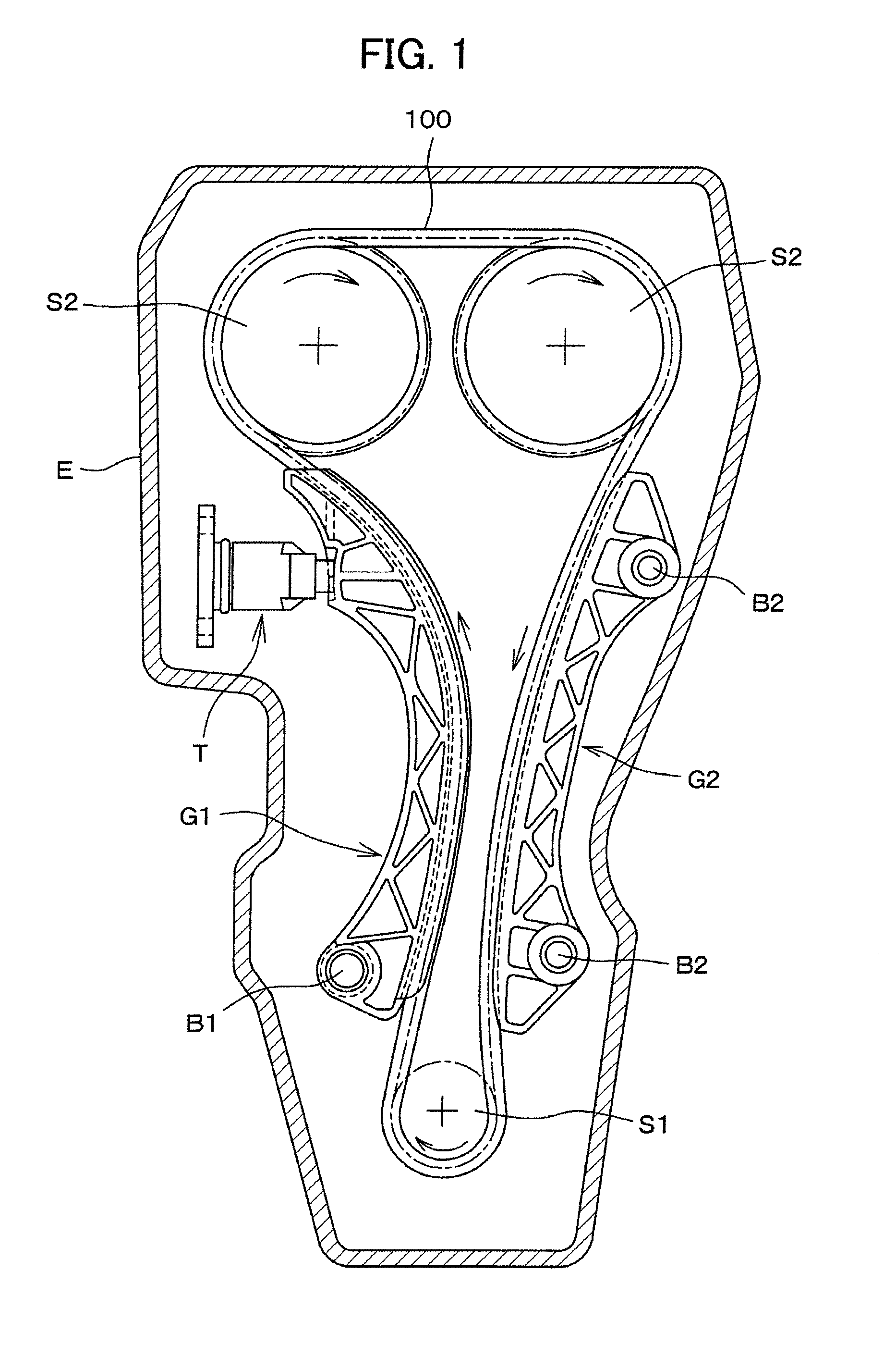
[0038]As shown in FIG. 1, a chain 100 is used in the timing drive of an engine E to transmit power from a crankshaft sprocket S1 to a pair of camshaft sprockets S2. The chain is in sliding contact with a tensioner lever G1 pivoted on bolt B1, and a fixed guide G2 mounted on bolts B2. A tensioner T maintains tension in the span of the chain that travels from sprocket S1 toward one of sprockets S2 by pressing against lever G1.

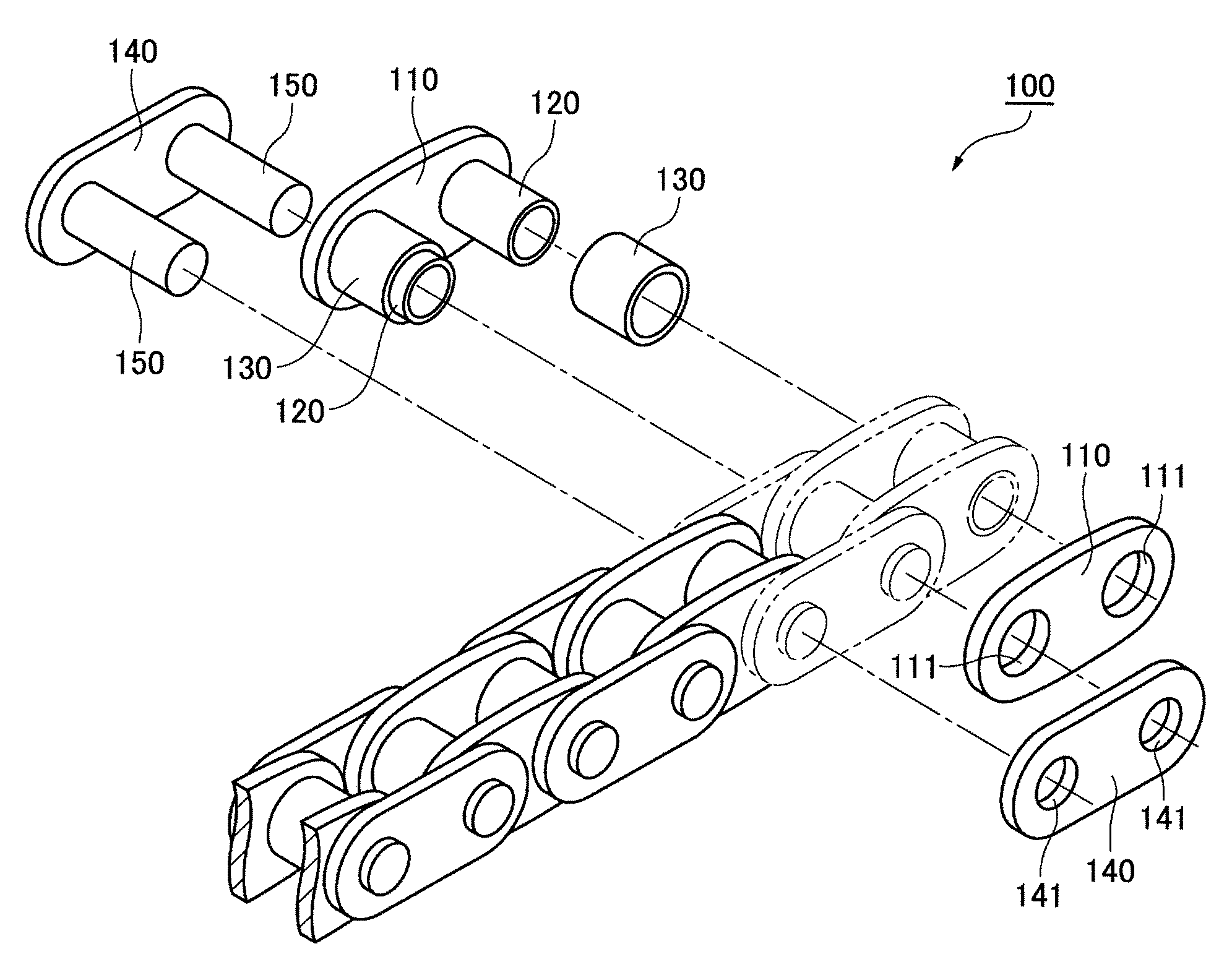
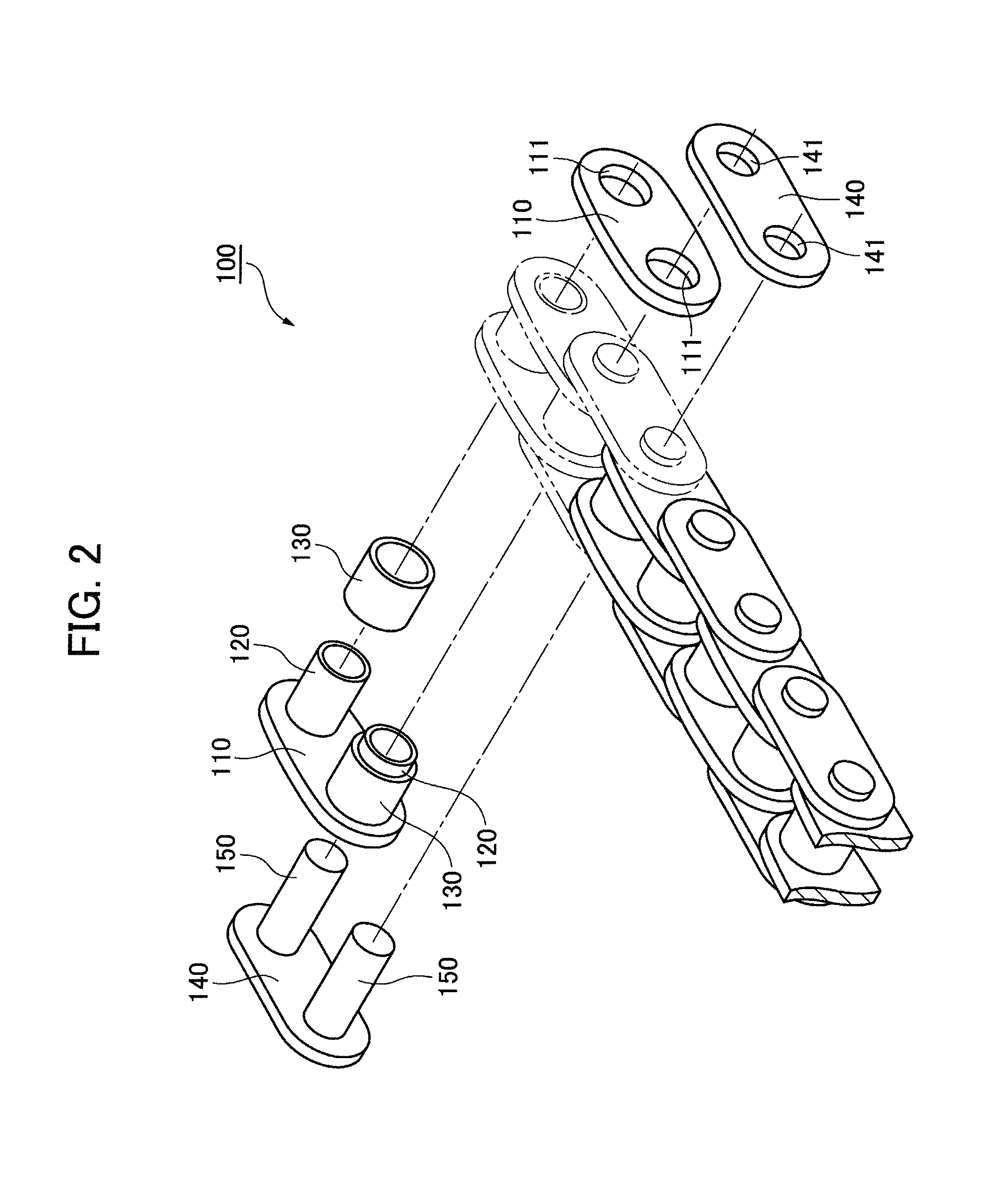
[0039]As shown in FIG. 2, the chain 100 comprises pairs of laterally spaced inner link plates 110 in side-by-side relationship. Opposite ends of cylindrical bushings 120 are press-fit into bushing holes 111 in the inner link plates. Rollers 130 fit rotatably around the bushings 120. The chain also includes pairs of laterally spaced outer link plates 140 also in side-by-side relationship and disposed in overlapping relationship with the inner link plates 110 on the outsides thereof. Connecting pins 150 are press-fit into pin holes 141 of the outer link plates 140,...


PUM


Abstract

In a roller or bushing chain, inner link plats have an oval shape, with a guide-contacting surface continuous with arc-shaped ends, and in the form of an arc having end points that are spaced from each other by a distance greater than the chain pitch but less than the greatest distance between parts of bushing holes in the inner link plates. The outer link plates have straight parallel edges parallel to the direction of chain elongation and semicircular ends continuous with the straight edges. The configuration of the inner link plates prevents the outer link plates from coming into contact with a chain guide.

Description

CROSS REFERENCE TO RELATED APPLICATIONS[0001]This application claims priority on the basis of Japanese patent application No. 2011-130180, filed on Jun. 10, 2011. The disclosure of Japanese patent application 2011-130180 is here incorporated by reference.FIELD OF THE INVENTION[0002]The invention relates to a power transmission chain such as a roller chain or a bushing chain for use in power transmission mechanisms of automobiles or industrial machinery.BACKGROUND OF THE INVENTION[0003]A conventional roller or bushing chain comprises alternating pairs of laterally spaced inner link plates and laterally spaced outer link plates. The inner link plates are connected by cylindrical bushings the ends of which are press-fit into the link plates, and the outer link plates are connected by connecting pins that are press fit into the outer link plates. The outer link plates are disposed in overlapping relationship with the inner link plates, and the connecting pins extend rotatably through th...

Claims


Application Information

Patent Timeline
Patent Type & Authority Applications(United States)
IPC IPC(8): F16G13/07
CPCF16G13/06F16H7/06
Inventor MIYAZAWA, TOSHIHIKO
Owner TSUBAKIMOTO CHAIN CO
Learn More