
Class e power amplifier

Active Publication Date: 2012-12-20
SEOUL NAT UNIV R&DB FOUND
View PDF6 Cites 19 Cited by
  • Summary
  • Abstract
  • Description
  • Claims
  • Application Information

AI Technical Summary

Benefits of technology

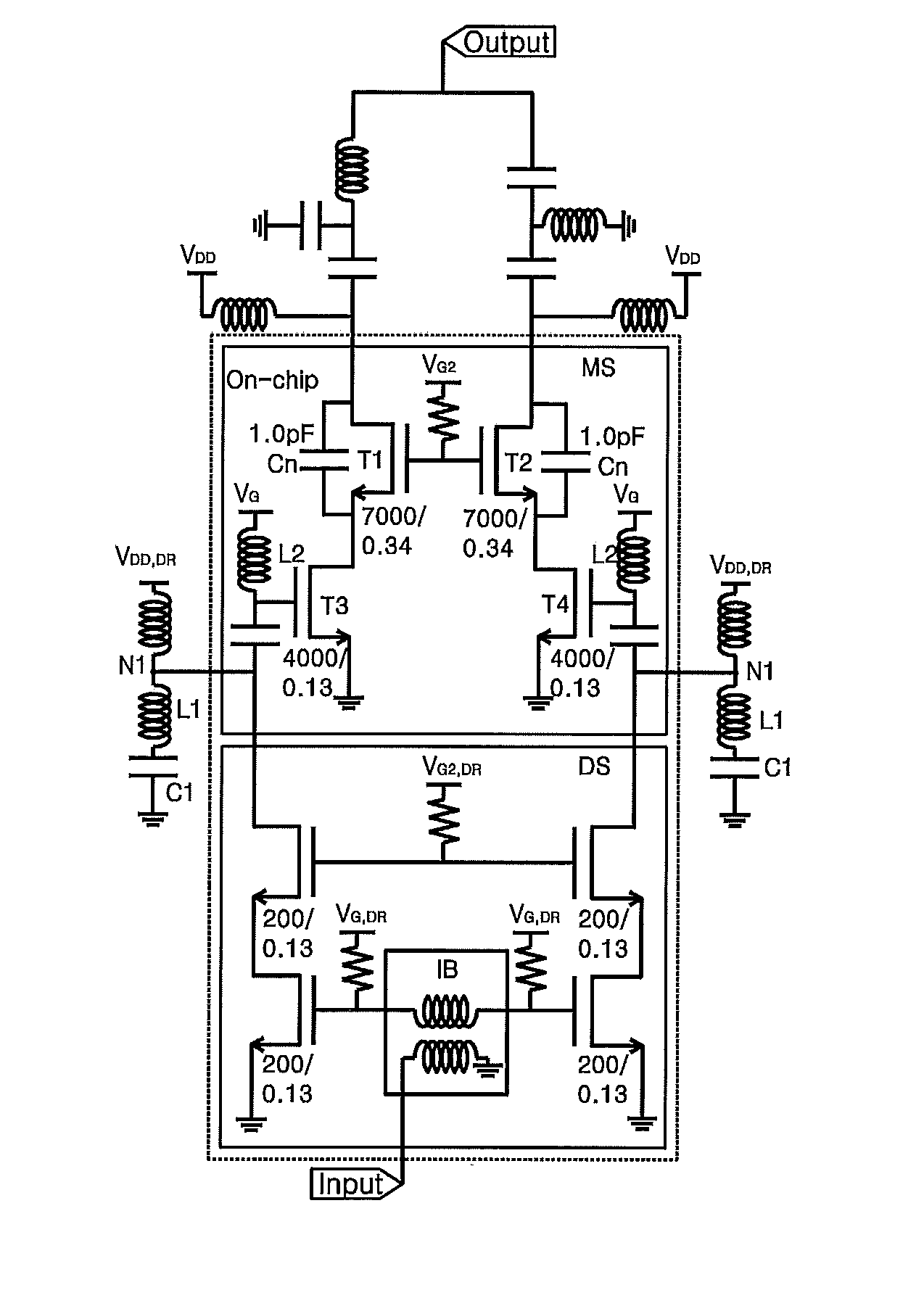
[0007]It is another object of the present invention to avoid breakdowns by implementing a double resonance circuit of a CMOS class-E power amplifier for harmonic control and reduce voltage stress on transistors by controlling voltage waveforms applied to the gate of the power amplifier and therefore to allow higher power supply voltage to be applied and get same efficiency even at a higher load impedance.
[0008]It is still another object of the present invention not only to deliver higher output power but also to minimize interference with other circuits in operation by applying a differential configuration, instead of a single ended configuration, to the CMOS class-E power amplifier.

Problems solved by technology

The CMOS power amplifier may reduce design costs but bring several problems.
One of the problems is a low breakdown voltage.
As the result, power supply voltage is limited to avoid breakdowns.
But this causes efficiency degradation and a narrowband load matching network.
Even though the gate width is widened, this causes parasitic elements such as parasitic capacitance.
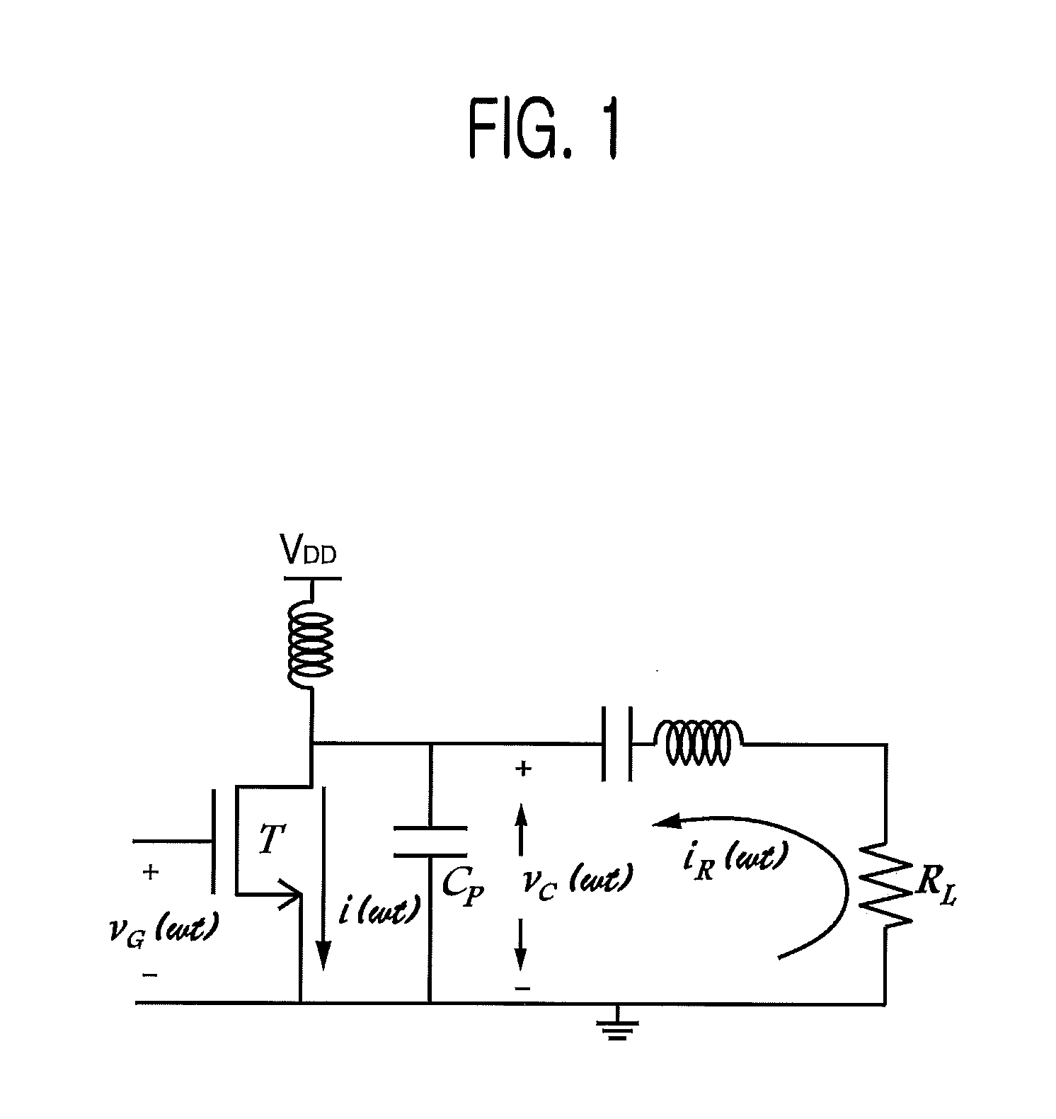
When the shunt drain capacitance CP deviates from the optimal value determined by the condition of the class-E power amplifier operation due to the parasitic capacitance, etc., the efficiency degradation occurs.

Method used


Image

  • Class e power amplifier
  • Class e power amplifier
  • Class e power amplifier

Examples


Embodiment Construction

[0025]The detailed description of the present invention illustrates specific embodiments in which the present invention can be performed with reference to the attached drawings.

[0026]In the following detailed description, reference is made to the accompanying drawings that show, by way of illustration, specific embodiments in which the invention may be practiced. These embodiments are described in sufficient detail to enable those skilled in the art to practice the invention. It is to be understood that the various embodiments of the invention, although different, are not necessarily mutually exclusive. For example, a particular feature, structure, or characteristic described herein in connection with one embodiment may be implemented within other embodiments without departing from the spirit and scope of the invention. In addition, it is to be understood that the location or arrangement of individual elements within each disclosed embodiment may be modified without departing from t...


PUM


Abstract

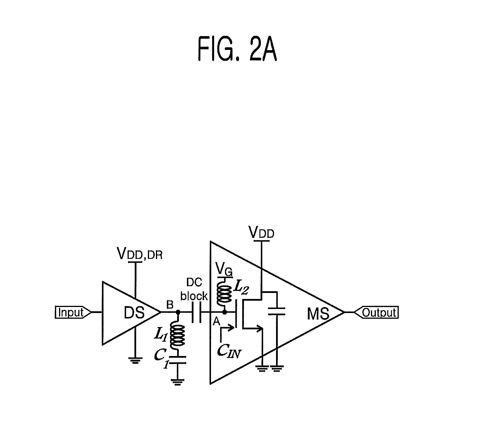
The present invention includes a class-E power amplifier, comprising a driver stage (DS) including a first power amplifier with transistors, to which an input signal is inputted; a main stage (MS), including a second power amplifier with transistors, whose input is connected to the output of the DS; and a first LC resonator whose one end is connected to the output of the DS and the other end to the ground as an AC equivalent circuit and a second LC resonator whose one end is connected to the input of the MS and the other end to the ground as an AC equivalent circuit. In accordance with the present invention, as the voltage stress is reduced on the CMOS class-E power amplifier, the application of the high power supply voltage may be allowed and therefore the load impedance may be high while the same efficiency is maintained.

Description

FIELD OF THE INVENTION[0001]The present invention relates to a class-E power amplifier; and more particularly, to a CMOS class-E power amplifier which improves overall efficiency and guarantees reliability with (i) harmonic-controlling double resonance circuit that reduces voltage stress on transistors and (ii) negative capacitance which compensates for surplus capacitance from the drain of the transistor.BACKGROUND OF THE INVENTION[0002]Recently, thanks to the development of telecommunication technology, mobile terminals, etc. are widely used. Such mobile terminals demand a high efficiency of transmitting RF signals. For the transmission of RF signals, the power amplifier which consumes the largest portion of DC power may be handled as the critical component to determine overall RF transmitter efficiency. Accordingly, power amplifiers with a high efficiency are necessary to improve overall efficiency[0003]In general, class-E power amplifiers are more widely used due to benefits suc...

Claims


Application Information

Patent Timeline
IPC IPC(8): H03F1/22H03F3/21
CPCH03F3/195H03F3/2176H03F1/223H03F2200/54H03F2200/06H03F2200/405H03F3/45179H03F3/217H03F3/20
Inventor NAM, SANG WOOKSONG, YONG HOONLEE, SUNG HOLEE, JAE JUNCHO, EUN IL
Owner SEOUL NAT UNIV R&DB FOUND
Learn More