Thermally Assisted Magnetic Head Assembly and Magnetic Disk Device
- Summary
- Abstract
- Description
- Claims
- Application Information
AI Technical Summary
Benefits of technology
Problems solved by technology
Method used
Image
Examples
embodiment 1
(1) Embodiment 1
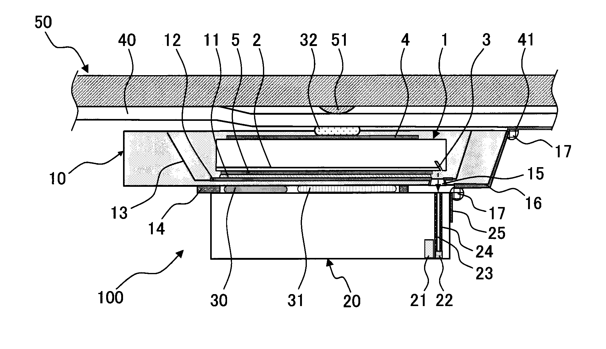
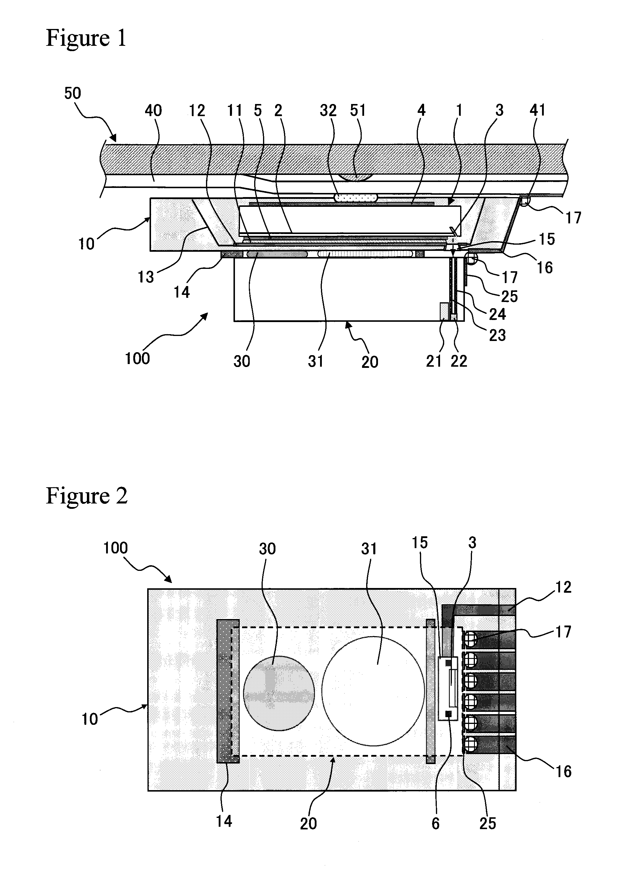
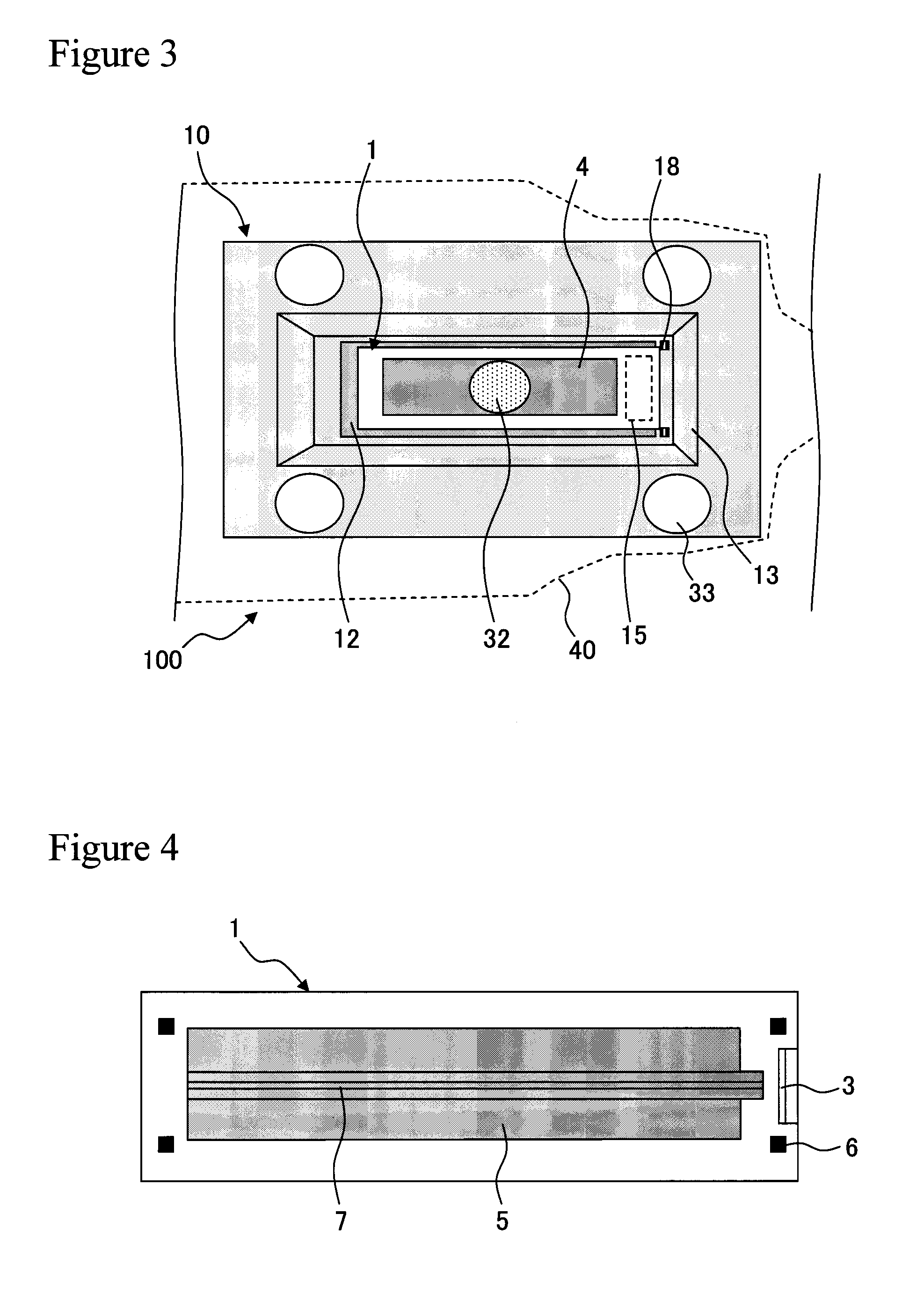
[0044]FIG. 1 illustrates a cross sectional structure example of a thermally assisted magnetic recording head assembly 100 according to Embodiment 1. As illustrated in FIG. 1, the thermally assisted magnetic recording head assembly 100 includes a submount 10, a slider 20, and two types of adhesives 30 and 31 which fix these members to each other. A through hole 15 is formed in the submount 10 so as to face an optical waveguide formed on the slider 20 side. A semiconductor laser 1 is mounted on the submount 10, and a reflection mirror 3 is formed in the semiconductor laser 1 so as to guide laser light to the through hole 15. Specifically, the reflection mirror 3 is formed near an end surface of the semiconductor laser 1. The optical waveguide (a core 23 and a clad 24), a near field generation element 22, and a magnetic recording / detection element 21 are mounted on the slider 20. At least part of the two types of adhesives 30 and 31 which fix the submount 10 and the sli...
embodiment 2
(2) Embodiment 2
[0065]FIG. 6 illustrates a planar structure example of the thermally assisted magnetic recording head assembly 100 according to Embodiment 2, which is observed from the slider 20 side. In the case of the present embodiment, the first adhesive 30 is applied a plurality of times (in the case of this figure, twice). This largely changes an apparent length of the first adhesive 30 in the short-side (width) direction of the slider 20. Normally, when an adhesive is applied by using a dispenser or the like, the adhesive is applied in the direction perpendicular to the submount 10 from the point of view of control. Therefore, the shape of the adhesive after application and mounting becomes a shape close to a circle. In the deformation of the slider 20, particularly, a change in the long-side direction has a more harmful influence on the floating property than a change in the short-side direction. In view of this, the first adhesive 30 is applied a plurality of times, to ther...
embodiment 3
(3) Embodiment 3
[0066]FIG. 7 illustrates a planar structure example of the thermally assisted magnetic recording head assembly 100 according to Embodiment 3, which is observed from the slider 20 side. The present embodiment adopts a structure in which the second adhesive 31 is surrounded by the stud 14. As a matter of course, the stud 14 is formed first. FIG. 8 illustrates a cross sectional structure example of the thermally assisted magnetic recording head assembly 100 according to the present embodiment. An adhesive not containing filler is used as the second adhesive 31, which enables a smaller thickness and a lower Young's modulus. In return, the viscosity becomes excessively low in some cases. In such a case, when the stud 14 is placed around the second adhesive 31, even if the second adhesive 31 spreads out at the time of application, the adhesive is prevented from flowing out of the slider 20, and the area thereof can be controlled to some degree.
PUM
 Abstract
Description
Claims
Application Information
 - R&D
- Intellectual Property
- Life Sciences
- Materials
- Tech Scout
- Unparalleled Data Quality
- Higher Quality Content
- 60% Fewer Hallucinations
Browse by: Latest US Patents, China's latest patents, Technical Efficacy Thesaurus, Application Domain, Technology Topic, Popular Technical Reports.
© 2025 PatSnap. All rights reserved.Legal|Privacy policy|Modern Slavery Act Transparency Statement|Sitemap|About US| Contact US: help@patsnap.com


