Supercharge Your Innovation With Domain-Expert AI Agents!

Machining method and machining apparatus of valve holes of cylinder head, and clamp device

Active Publication Date: 2012-12-27
HONDA MOTOR CO LTD
View PDF6 Cites 2 Cited by
  • Summary
  • Abstract
  • Description
  • Claims
  • Application Information

AI Technical Summary

Benefits of technology

[0009]In addition, embodiments of the invention provide a clamp device that can change a shift amount of a workpiece with a simple configuration.

Problems solved by technology

However, it is difficult to machine a plurality of intake valve holes and a plurality of exhaust valve holes which are formed on one cylinder with single processing, since the valve holes are proximately adjacent to each other.
Therefore, there are problems in that the number of the multi-spindle heads increases, the operation becomes complicated, and the steps of the machining process increase.
However, when an actuator for changing the amount of shift is provided, there is a problem in that the configuration of the apparatus becomes complicated.

Method used


Image

  • Machining method and machining apparatus of valve holes of cylinder head, and clamp device
  • Machining method and machining apparatus of valve holes of cylinder head, and clamp device
  • Machining method and machining apparatus of valve holes of cylinder head, and clamp device

Examples


Embodiment Construction

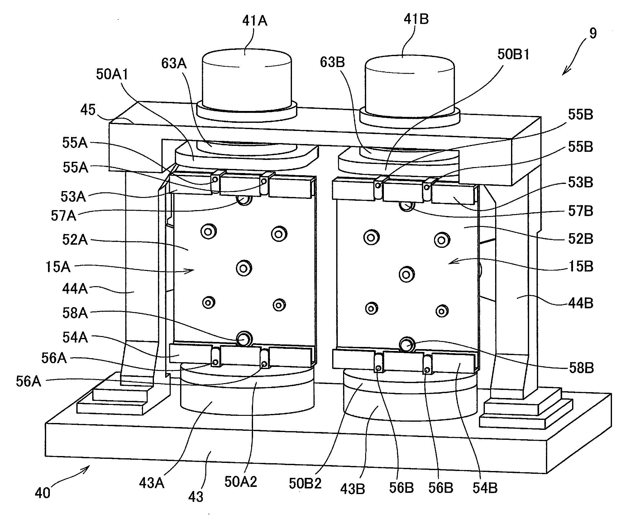
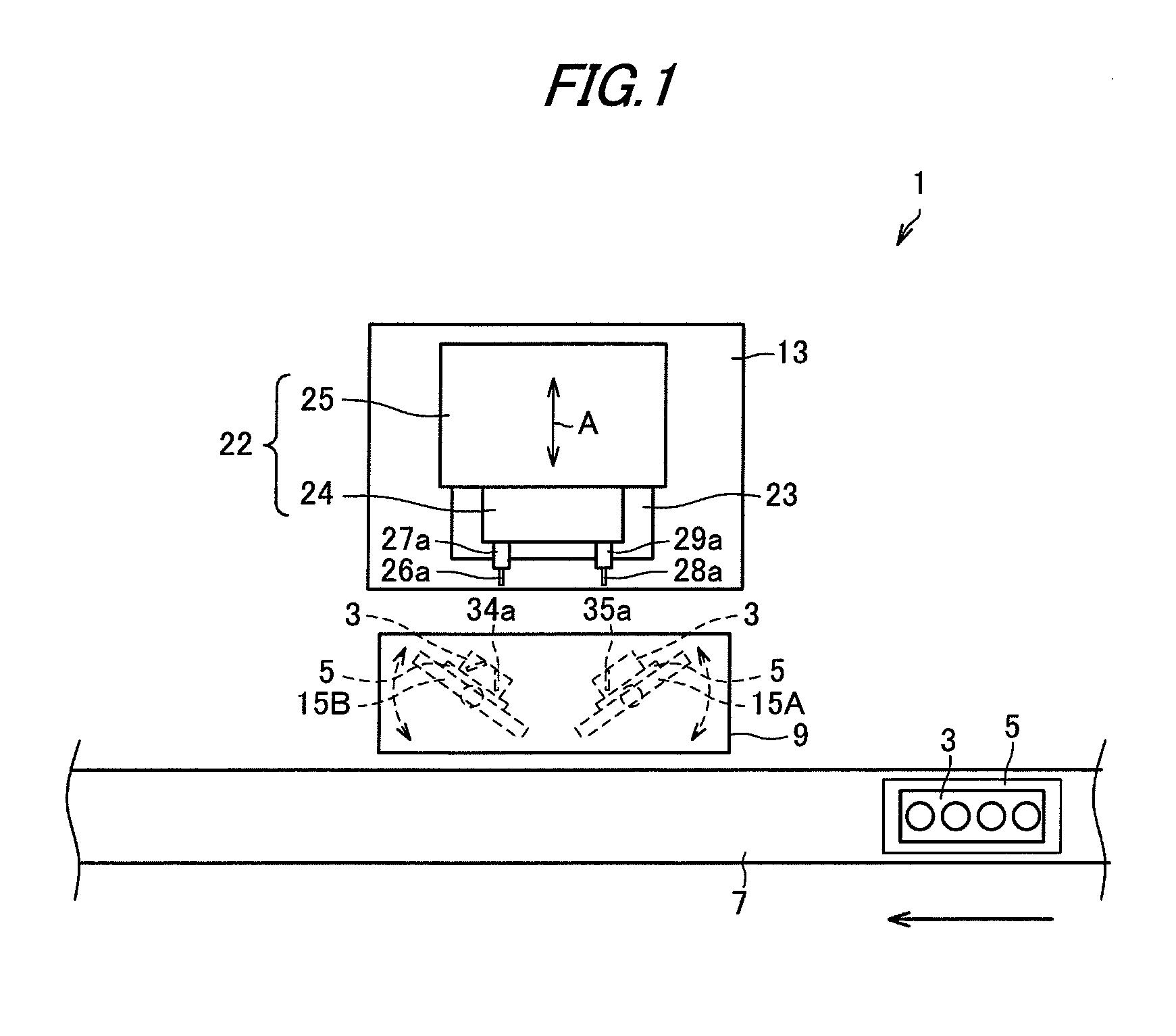
[0024]FIG. 1 is a schematic configuration view of an apparatus for machining valve holes according to an exemplary embodiment of the invention. In FIG. 1, reference numeral 1 indicates an apparatus for machining valve holes. The apparatus for machining valve holes 1 includes a conveyor 7, which conveys a pallet 5 on which a cylinder head (workpiece) 3 is loaded, a clamp device 9, which fixes the cylinder head 3 conveyed on the conveyor 7 together with the pallet 5, and a machine tool 13, which is disposed opposite the clamp device 9, and has a plurality of tools for machining valve holes in the cylinder head 3.

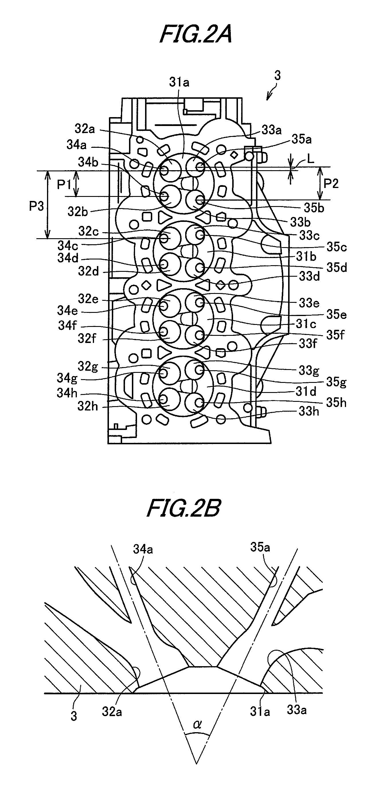
[0025]The clamp device 9 is disposed between the conveyor 7 and the machine tool 13, and includes a pair of left and right jig bodies (bodies) 15A and 15B to which the cylinder head 3 is fixed in the state in which the cylinder head 3 is loaded on the pallet 5. The respective jig bodies 15A and 15B are configured such as to be rotatable around a rotary shaft that extends in th...


PUM

PropertyMeasurementUnit
Timeaaaaaaaaaa
Timeaaaaaaaaaa
Timeaaaaaaaaaa

Abstract

Two cylinder heads (3, 3) are disposed side by side. Upper side intake valve holes (34a, 34c, 34e, 34g) of one of the cylinder heads (3) and upper side exhaust valve holes (35a, 35c, 35e, 35g) of the other of the cylinder heads (3) are simultaneously machined by a multi-spindle head (24) integrally including intake side tools (26a to 26d) and exhaust side tools (28a to 28d). After moving the one of the cylinder heads (3) upward by a pitch P1 of the intake valves and moving the other of the cylinder heads (3) upward by a pitch P2 of the exhaust valves, remaining intake valve holes (34b, 34d, 34f, 34h) of the one of the cylinder heads (3) and remaining exhaust valve holes (35b, 35d, 35f, 35h) of the other of the cylinder heads (3) are simultaneously machined.

Description

TECHNICAL FIELD[0001]The present invention relates to a method and apparatus for machining valve holes of a cylinder head of an internal combustion engine.[0002]The present invention also relates to a clamp device that holds a workpiece while the workpiece is being machined.BACKGROUND ART[0003]In general, in a workpiece such as a cylinder head that constitutes an engine, a plurality of valve holes to which intake valves and exhaust valves are attached are provided for a single cylinder (see, for example, Patent Document 1). When machining the plurality of valve holes in the cylinder head, it is preferable that the valve holes are machined by a small number of processes and with high precision.[0004]In order to simultaneously machine a plurality of valve holes, it is considered to use a so-called gang head (multi-spindle head), in which, for example, a plurality of tools for performing reamer machining is rotatably provided. However, it is difficult to machine a plurality of intake v...

Claims


Application Information

Patent Timeline
IPC IPC(8): B23P11/00B23Q1/64
CPCB23B41/12B23Q39/028B23C3/05B23Q2039/006B23B39/20Y10T408/3809Y10T29/51Y10T408/385Y10T408/5614Y10T29/4927Y10T408/03B23B2215/24
Inventor SAKAI, DAIKIIMABUCHI, KENICHIISHII, TETSUOINAKI, KATSUMUNEARAKAWA, SHUGOITO, KAZUHIDEKASHIWAGI, HIROSHIKANEKO, MASAYUKI
Owner HONDA MOTOR CO LTD
Features
  • R&D
  • Intellectual Property
  • Life Sciences
  • Materials
  • Tech Scout
  • Unparalleled Data Quality
  • Higher Quality Content
  • 60% Fewer Hallucinations
Learn More