
Signal Light Priority System Utilizing Estimated Time of Arrival

a priority system and signal light technology, applied in the direction of road vehicle traffic control, traffic signal control, instruments, etc., can solve the problems of increased greenhouse gas emissions, long running times, and traffic delays affecting productivity and economic efficiency

Active Publication Date: 2012-12-27
STC INC
View PDF10 Cites 61 Cited by
  • Summary
  • Abstract
  • Description
  • Claims
  • Application Information

AI Technical Summary

Benefits of technology

"The patent describes methods and systems for controlling traffic lights based on a vehicle's location and estimated time of arrival. This helps the vehicle reach its destination on time. The technical effect of this patent is to improve traffic flow control systems by utilizing real-time data to modify priority management cycles of multiple traffic lights."

Problems solved by technology

Moreover, traffic delays impinge on productivity and economic efficiency—time spent traveling to and from work is not time spent doing work.
Traffic delays all of these economic production factors.
Further, longer commutes means longer running times and entails more greenhouse gases.
Also, congested traffic and uncoordinated signal lights can cause delays in the mass transit system which, if not remedied, can throw off an entire mass transit schedule grid and disincentivise individuals from using mass transit systems.
For example, it has been demonstrated that schedule adherence for mass transit vehicles results in an increase in ridership.
Lastly, the importance of prioritizing and efficiently moving emergency vehicles through traffic lights is axiomatic.
While this type of control mechanism can be effective in one-way grids where it is often possible to coordinate signal lights to the posted speed limit, this control mechanism is not advantageous when the signal timing of the intersection would benefit from being adapted to the changing flows of traffic throughout the day.
Two-way streets are more complicated, but often end up being arranged to correspond with rush hours to allow longer green light times for the heavier volume direction.
While cascading or synchronized central control systems are an improvement on the traditional timer controlled systems, they still have their drawbacks.
Namely, priority vehicles in these systems are only able to interact with a virtual detection zone immediately preceding a particular intersection; there is no real-time monitoring of the traffic flows preceding or following this virtual detection zone across a grid of multiple signal lights.
Accordingly, these systems can provide for a priority vehicle, such as an emergency vehicle, to be accelerated through a particular signal at the expense of other vehicles, but they lack the capability to adapt and adjust traffic flows to keep a mass transit vehicle, or similar time scheduled vehicle, on time or adjust the lights in front of a mass transit vehicle to get it back on schedule.
Virtual detection zone based systems only have the capability for control of a particular signal light to accelerate the movement of a single vehicle or a group of vehicles approaching that signal directly; they cannot offer an integrated control system with the capability of controlling the phases of multiple signal lights in a grid system, altering the length of particular phases at particular signal lights within the grid system to accommodate a particular vehicle traveling through the grid system according to a relatively fixed path and schedule.
Another problem with virtual detection zone based systems is their disruption of the overall traffic flow of the grid.
If a priority vehicle is sensed in the virtual detection zone, the immediately upcoming light will either change to green to give the priority vehicle the right-of-way and potentially disrupt the entire system (something logical for allowing rapid passage of an emergency vehicle) or will not because the vehicle lacks sufficient priority to disrupt the system (as can be the case with a mass transit vehicle) simply to beat the next signal.
What detection zone based systems fail to take into account is the impact this immediate change in an immediately approached signal light phase, irrespective of other traffic at the light, has on the overall traffic flows of the grid as a whole.
Further, because of their focus on a single signal light and vehicles approaching a single signal light, these systems are generally incapable of adjusting a series of lights within the traffic grid based upon a vehicle's current position, speed, schedule and path of travel.
Another frequent traffic problem which cannot be addressed by these commonly utilized virtual detection zone based systems is mass transit vehicle bunching, also known as bus bunching, clumping or platooning.
Thus, the lead mass transit vehicle in the bunch typically slows to pick up passengers that would otherwise be boarding the trailing mass transit vehicle.
This leads to overcrowding and further slowing of the lead vehicle.
Conversely, the trailing mass transit vehicle encounters fewer passengers and, soon, both mass transit vehicles are in full view of each other—to the dismay of passengers on the overcrowded and behind schedule vehicles.
It is no surprise that bunching is a leading complaint of regular transit riders and a headache for those operating and managing transit services.
The currently utilized detection zone based systems—with their control methodology localized to individual lights—are simply incapable of controlling or preventing bunching.
Another failing of the currently utilized detection zone based systems is their inability to modify the conditions under which a vehicle may request priority.
These systems are generally incapable of granting priority on a more nuanced and conditional basis such as only granting priority when another mass transit vehicle has not requested priority within a specified time frame or only granting priority when an exit request has not been made for the next stop.

Method used


Image

  • Signal Light Priority System Utilizing Estimated Time of Arrival
  • Signal Light Priority System Utilizing Estimated Time of Arrival
  • Signal Light Priority System Utilizing Estimated Time of Arrival

Examples


Embodiment Construction

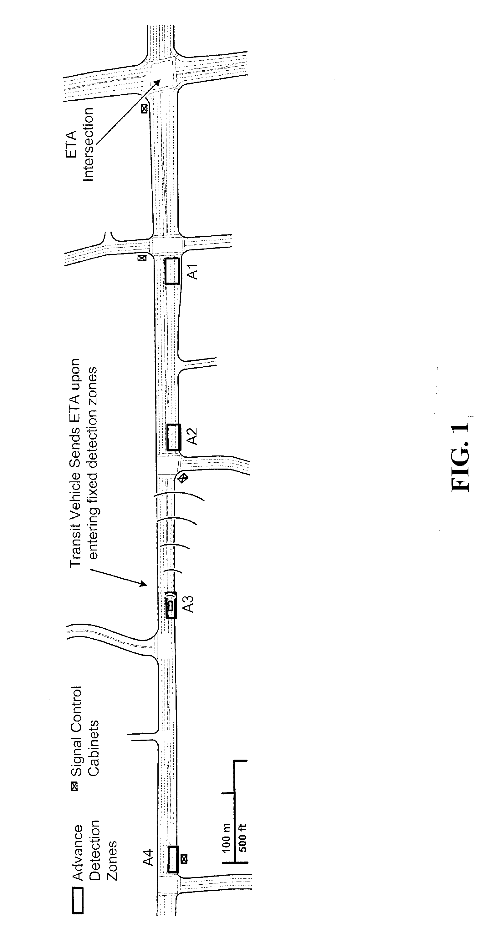
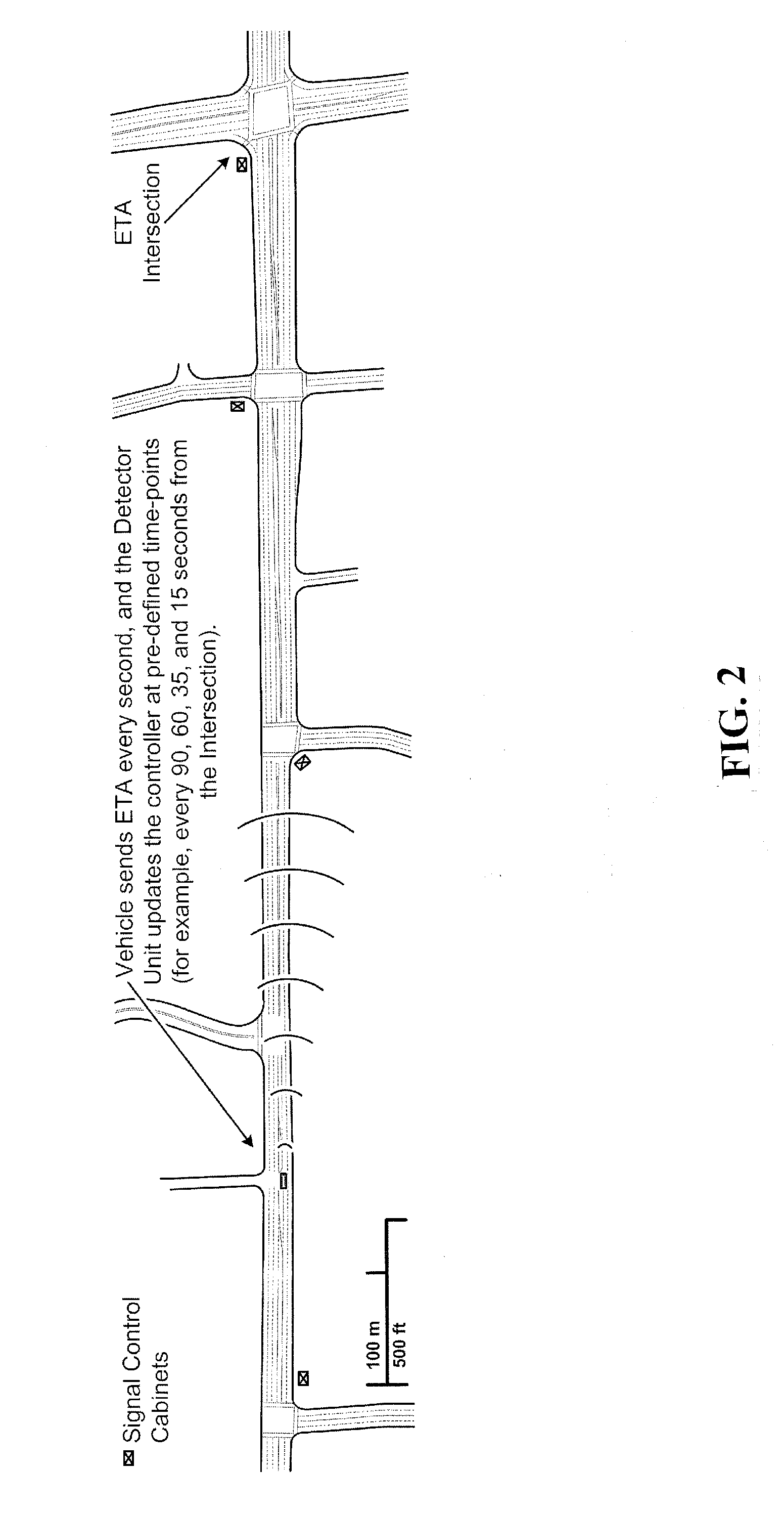
[0033]This disclosure is intended to teach by way of example and not by way of limitation. As a preliminary matter, it should be noted that while the description of various embodiments of the disclosed system will discuss the movement of mass transit vehicles (such as, but not limited to, buses, light rail trains, and street cars) through signal lights, this in no way limits the application of the disclosed traffic control system to use in mass transit systems. Any vehicle which could benefit from the ETA traffic control system described herein is contemplated. For example, it is contemplated that the system could be applied to and utilized by taxis, first responders, emergency vehicles, snow plows and waste management vehicles.

[0034]In a broad sense, the ETA traffic control system combines satellite position navigation systems and dead reckoning technology with secure radio communications to accurately report a vehicle's real-time location and estimated arrival times at a series of...


PUM


Abstract

Systems and methods for requesting modification of traffic flow control systems that combine satellite position navigation systems and dead reckoning technology with secure radio communications to accurately report a vehicle's real-time location and estimated arrival times at a series of signal lights within a traffic grid or at a distant signal light, while enabling signal controllers to accommodate priority requests from these vehicles, allowing for these vehicles to maintain a fixed schedule with minimal interruption to other grid traffic.

Description

CROSS REFERENCE TO RELATED APPLICATION(S)[0001]This Application claims the benefit of U.S. Provisional Patent Application Ser. No. 61 / 501,373, filed Jun. 27, 2011, the entire disclosure of which is incorporated herein by reference.BACKGROUND OF THE INVENTION[0002]1. Field of the Invention[0003]This disclosure is related to the field of systems for the management of traffic flow through the controlling of signal lights and monitoring the location of vehicles within a traffic grid.[0004]2. Description of Related Art[0005]In the perfect commuter utopia, signal lights would automatically switch to green every time a driver's vehicle approached an intersection, creating an unobstructed pathway towards the driver's final destination. In real life though, hitting a red light is a normal and inevitable part of any driver's commute. With the growth of modern cities and the reliance of much of the population on mass transit and personal automobiles for transportation, efficient control of the...

Claims


Application Information

Patent Timeline
Patent Type & Authority Applications(United States)
IPC IPC(8): G08G1/087
CPCG08G1/087G08G1/082
Inventor CROSS, BRAD
Owner STC INC
Learn More