Dispenser for chemical-mechanical polishing (CMP) apparatus, cmp apparatus having the dispenser, and cmp process using the cmp apparatus

Active Publication Date: 2012-12-27
UNITED MICROELECTRONICS CORP
View PDF4 Cites 0 Cited by
  • Summary
  • Abstract
  • Description
  • Claims
  • Application Information

AI Technical Summary

Benefits of technology

[0010]According to the dispenser for a CMP apparatus, the CMP apparatus having the dispenser, and the CMP process using the CMP apparatus provided by the present invention, the first openings connected to the slurry delivery grooves uniformly distribute the slurry to the polishing pad. Therefore removal rates on different regions of the polishing pad are averaged while the removal rates are all improved. Accordingly, surface planarity of the wafer being polished and the process efficiency of CMP adopting the provided CMP apparatus are both improved.

Problems solved by technology

Consequently, the topmost surface of the substrate may become non-planar across its surface and requires planarization.
One problem is encountered in the CMP process using the conventional CMP apparatus when the slurry is delivered to the center of the polishing pad.
In detail, because the slurry is delivered to only the center of the polishing pad in the conventional CMP apparatus, the slurry is not uniformly distributed.
Accordingly, both general decrease in removal rate and lack of uniformity in removal rate on different regions of the polishing pad are caused.
Accordingly, significant and costly reduction in CMP process efficiency and product quality are resulted.

Method used


Image

  • Dispenser for chemical-mechanical polishing (CMP) apparatus, cmp apparatus having the dispenser, and cmp process using the cmp apparatus
  • Dispenser for chemical-mechanical polishing (CMP) apparatus, cmp apparatus having the dispenser, and cmp process using the cmp apparatus
  • Dispenser for chemical-mechanical polishing (CMP) apparatus, cmp apparatus having the dispenser, and cmp process using the cmp apparatus

Examples


Embodiment Construction

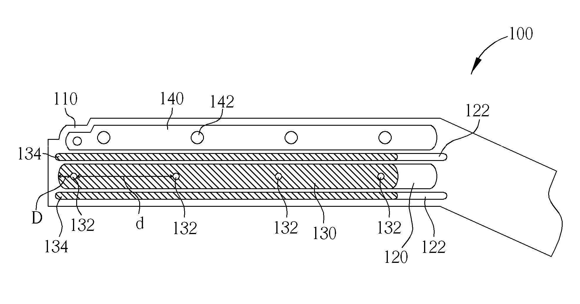
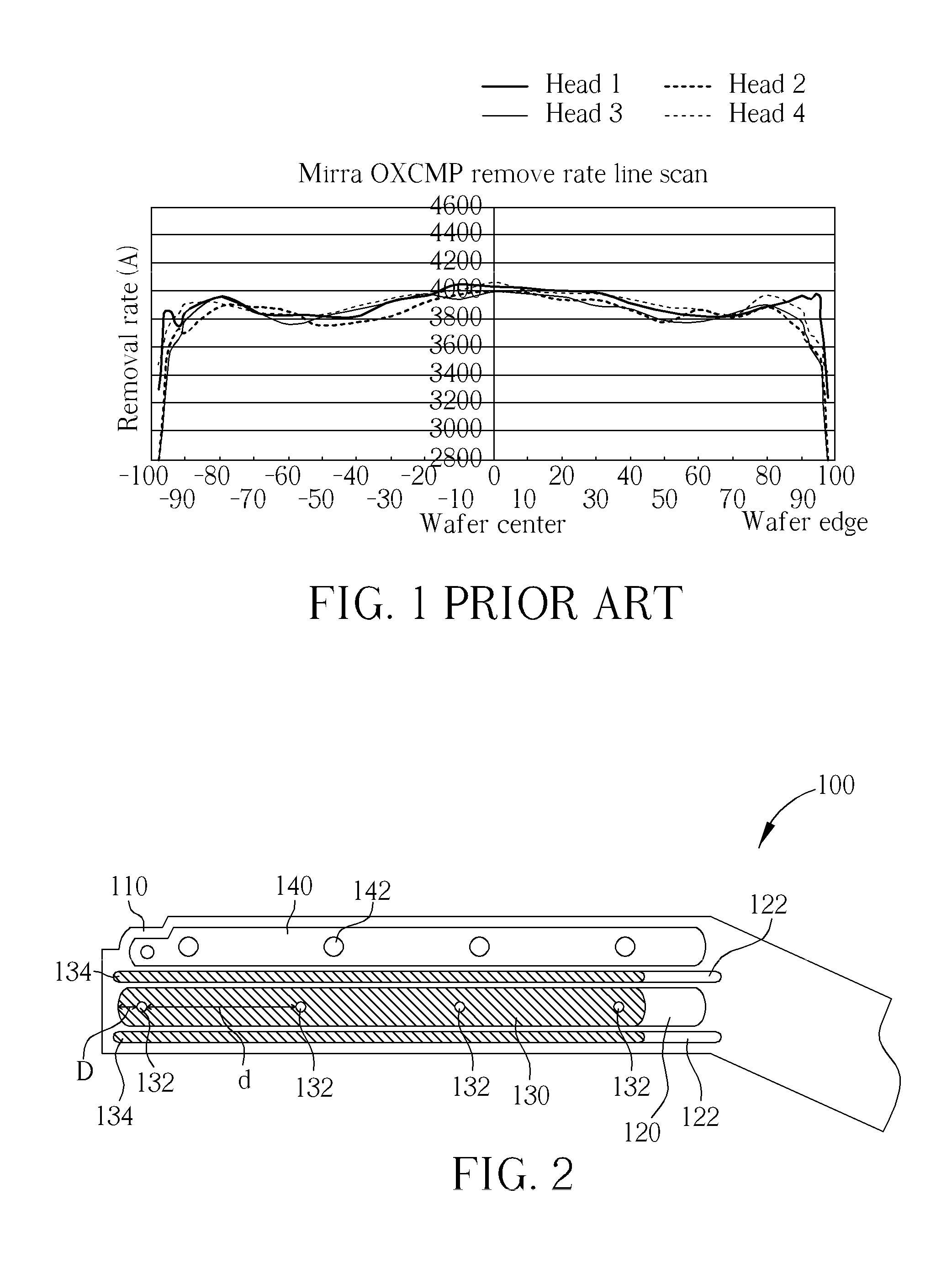
[0018]Please refer to FIG. 2, which is schematic drawing illustrating a dispenser for a CMP apparatus provided by a preferred embodiment of the present invention. As shown in FIG. 2, the preferred embodiment provides a dispenser 100 for a CMP apparatus. The dispenser 100 serves to provide slurry and cleaning fluid used in CMP process, and the slurry, usually either is basic or acidic, exemplarily includes a reagent, frictional particles, and chemical reaction catalyst. The dispenser 100 includes a delivery arm 110, at least a slurry delivery groove 120 formed in the delivery arm 110 and extending along a length of the delivery arm 110, and a plurality of first openings 132 connected to the slurry delivery groove 120. In this preferred embodiment, an amount of the first openings 132 is exemplarily four, but not limited to this. It should be appreciated that the amount of the first openings 132 can be increased or reduced to fit the needs of different applications. It is noteworthy th...


PUM


Abstract

A dispenser for a chemical-mechanical polishing (CMP) apparatus, includes a delivery arm disposed over a polishing pad of a CMP apparatus, at least a slurry delivery groove formed in the delivery arm and extending along a length of the delivery arm, and a plurality of first openings connected to the slurry delivery groove.

Description

BACKGROUND OF THE INVENTION[0001]1. Field of the Invention[0002]The present invention generally relates to a dispenser for a chemical-mechanical polishing (hereinafter abbreviated as CMP) apparatus, a CMP apparatus having the dispenser, and a CMP process using the CMP apparatus, and more particularly, to a slurry and rinse dispenser for a CMP apparatus, a CMP apparatus having the dispenser, and a CMP process using the CMP apparatus.[0003]2. Description of the Prior Art[0004]Integrated circuits (ICs) are typically formed on substrates, exemplarily silicon wafers, by sequential deposition of conductive, semi-conductive or insulating layers. After depositing the required layer, etching process is often performed to create circuitry features and followed by another film formation. Consequently, the topmost surface of the substrate may become non-planar across its surface and requires planarization.[0005]CMP is one accepted method of planarization and now typically employed in the indust...

Claims


Application Information

Patent Timeline
IPC IPC(8): H01L21/306B24B57/00
CPCB24B57/02B24B3/02H01L21/32115H01L21/3212H01L21/67051H01L21/6708
Inventor HAM, LIANG-CHUOCHIH, CHIN-CHUANLEE, JIANN-MOYANG, CHIA-MINGCHEN, WEN-YEN
Owner UNITED MICROELECTRONICS CORP
Why Eureka
Try Eureka