Biomedical Interface Pressure Transducer for Medical Tourniquets

a biomedical interface and pressure transducer technology, applied in the field of transducers, can solve the problems of affecting the local stress field, affecting the safety of patients, and affecting the safety of patients, and achieve the effect of low cos

Inactive Publication Date: 2012-12-27
ABATIS MEDICAL TECH
View PDF12 Cites 2 Cited by
  • Summary
  • Abstract
  • Description
  • Claims
  • Application Information

AI Technical Summary

Benefits of technology

[0016]This invention is directed towards providing an improved transducer for measuring biomedical interface pressures and pressure gradients at any interface between a

Problems solved by technology

In many practical instances of pneumatic tourniquet use, P is assumed to be equal to π. However, there are situations where this assumption may not be valid.
In such cases hazard conditions can arise due to discrepancies between the indicated cuff pressure, π, and the actual applied pressure P. For instance, the outer walls of some pneumatic cuffs have integrated stiffener layers designed to stabilize and restrict radial expansion of the cuff when fitted to a supporting limb.
Such folding and creasing complicates the local stress field which may have significant orientation and magnitude variation producing wrinkling and pinching of the support tissue.
However, such interventions may produce an offset or residual non-pneumatic pressure of unknown value resulting in a discrepancy between tourniquet pressure, π, and actual applied pressure, P. Again, such non-pneumatic pressures may be sufficiently high to restrict venous return from the supporting limb and impede the flow of arterial blood into the limb.
However, real limbs do not have regular geometric shapes and so the pressure will vary locally with curvature.
In addition, the actual membrane tension may not be measured or known.
Pressures calculated using the law of Laplace cannot be expected to accurately reflect the actual sub-tourniquet pressure at a given location on a limb or support tissue nor can such calculations provide a dynamic indication of the actual pressure applied by the tourniquet as limb position and orientation changes.
A major criticism of such tourniquets used to restrict arterial blood flow, is that, if not properly applied, tourniquets can actually increase bleeding by occluding venous return while not completely arresting arterial flow {Doyle and Taillac, “Tourniquets: A Review of Current Use with Proposals for Expanded Prehospital Use”, Prehospital Emergency Care, V12, 2008, 241-54}.
The risk of tourniquet-related nerve injury continues to be a serious concern.

Method used


Image

  • Biomedical Interface Pressure Transducer for Medical Tourniquets
  • Biomedical Interface Pressure Transducer for Medical Tourniquets
  • Biomedical Interface Pressure Transducer for Medical Tourniquets

Examples


Embodiment Construction

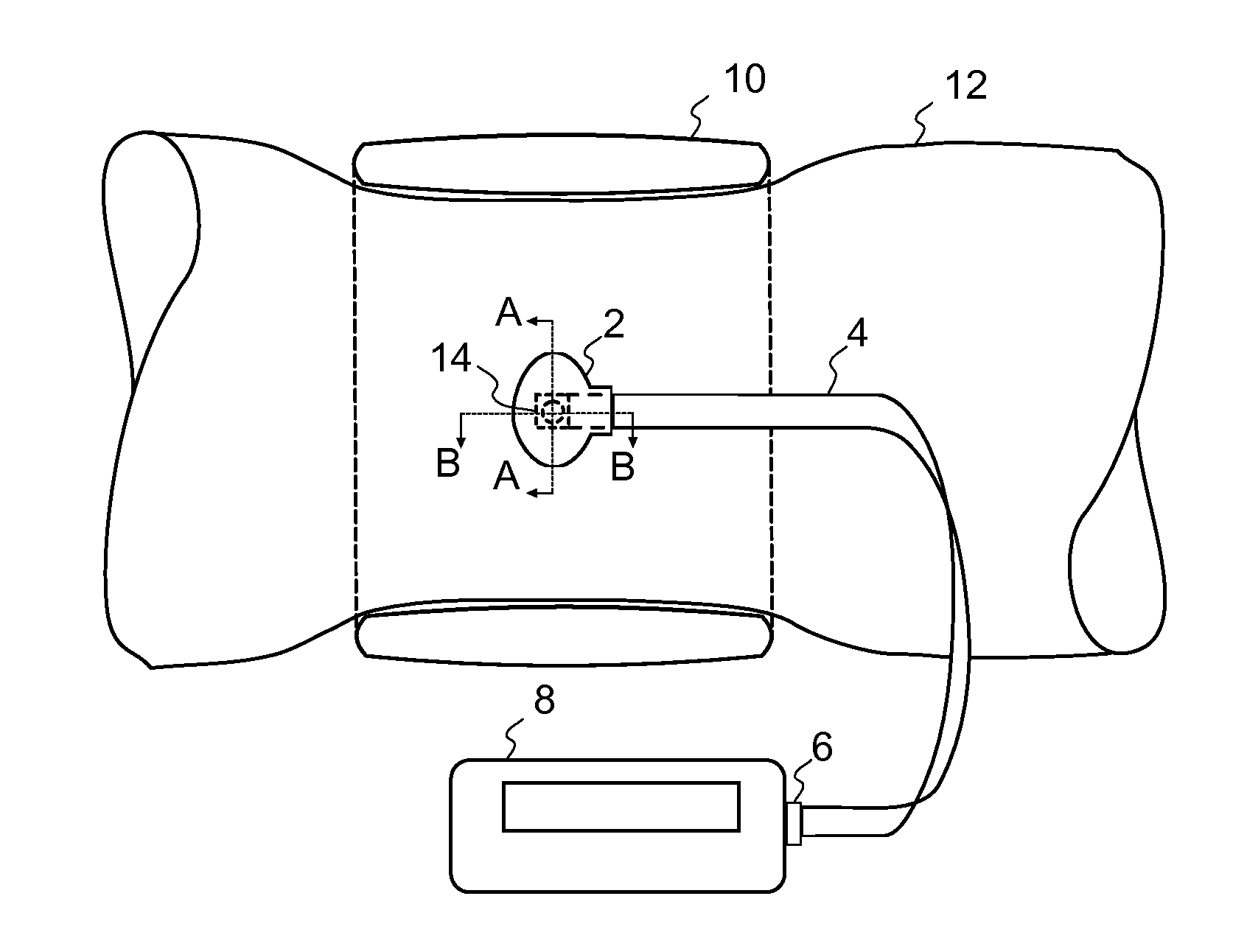
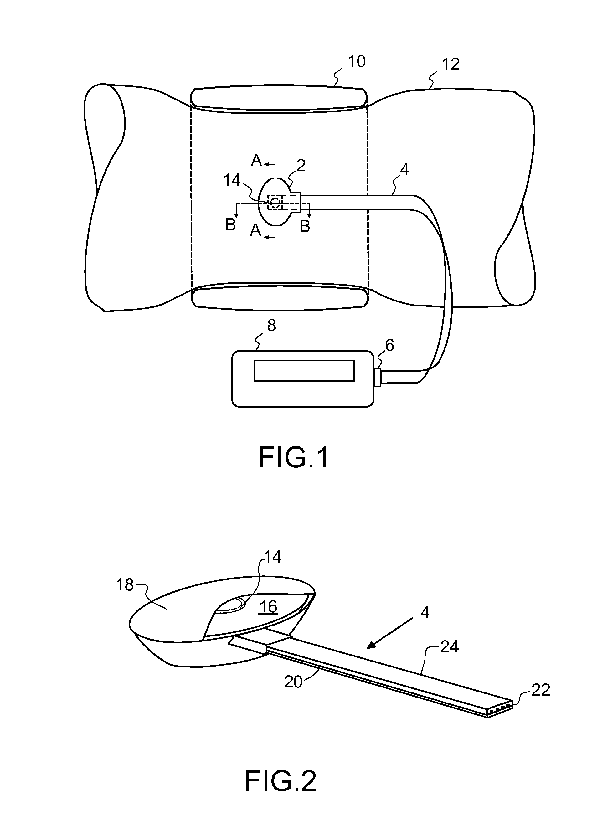
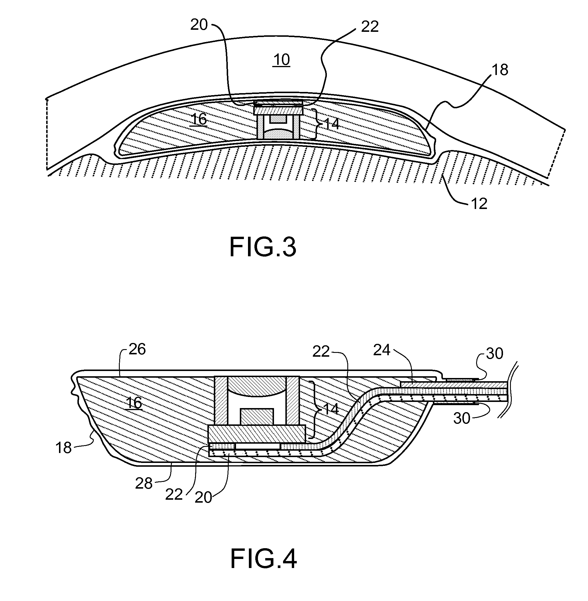
[0028]A biomedical interface pressure transducer apparatus is shown in FIG. 1 and consists of: biomedical interface pressure transducer 2, flexible interconnector assembly 4, connector 6 and control means 8. The biomedical interface pressure transducer 2 is disposed between a pneumatic tourniquet 10 and a limb 12 and incorporates a modified MEMS pressure sensor 14. The transducer may be positioned at a desired location under the tourniquet using medical adhesive tape or adhesive pads.

[0029]In overview, the pneumatic tourniquet 10 applies pressure to the enclosed limb 12. The biomedical interface pressure transducer 2 is located at the interface between the pneumatic tourniquet 10 and the limb surface. Control means 8 includes a user interface that permits a user to control the operation of the biomedical interface pressure transducer 2. The control means 8 displays relevant information regarding the operation of the biomedical interface pressure transducer 2 to the user. The user in...


PUM


Abstract

A biomedical interface pressure transducer which is useful for interposing between a limb or tissue and an occlusive band, tourniquet cuff or other biomedical apparatus in order to estimate the pressure and pressure gradient applied to a selected area of the limb or tissue is disclosed. The pressure transducer comprises a modified MEMS pressure sensor and a conformable semisolid body enclosed in a shear relief membrane which translates the pressure applied by the occlusive band to the modified MEMS pressure sensor mounted on a flexible substrate with patterned electrical interconnect tracks allowing the connection of the pressure sensor to digital communication and control circuitry.

Description

FIELD OF THE INVENTION[0001]This invention pertains to transducers for estimating the pressure and pressure gradients applied to body-tissue by an object such as pneumatic tourniquet used in surgical procedures and in tactical and civilian emergency medical services (EMS).BACKGROUND OF THE INVENTION[0002]The pressure, P, developed beneath a pneumatic tourniquet cuff is largely governed by the gas or fluid pressure π in the tourniquet, which is assumed to act normally to the local support surface. In many practical instances of pneumatic tourniquet use, P is assumed to be equal to π. However, there are situations where this assumption may not be valid. In such cases hazard conditions can arise due to discrepancies between the indicated cuff pressure, π, and the actual applied pressure P. For instance, the outer walls of some pneumatic cuffs have integrated stiffener layers designed to stabilize and restrict radial expansion of the cuff when fitted to a supporting limb. The overall cu...

Claims


Application Information

Patent Timeline
IPC IPC(8): A61B5/00
CPCA61B2019/465A61B2562/0247A61B17/135A61B5/02233A61B2090/065
Inventor CASEY, VINCENT
Owner ABATIS MEDICAL TECH
Why Eureka
Try Eureka