System for reducing engine emissions and backpressure using parallel emission reduction equipment

a technology of backpressure and emission reduction equipment, which is applied in the direction of machines/engines, mechanical equipment, electric control, etc., can solve the problems of limited space available for adding new system components and high fuel efficiency, and achieve the effects of reducing nox emissions, reducing engine exhaust emissions, and reducing hydrocarbon and/or carbon monoxide emissions

Active Publication Date: 2013-01-03
ELECTRO-MOTIVE DIESEL
View PDF23 Cites 13 Cited by
  • Summary
  • Abstract
  • Description
  • Claims
  • Application Information

AI Technical Summary

Benefits of technology

[0013]In accordance with a further aspect of the present disclosure, a method is provided of reducing engine exhaust emissions in an internal combustion engine having a plurality of cylinders for combusting fuel with air, the combustion producing exhaust gases. One or more components are provided for reducing NOx emissions and one or more filtration components are provided for reducing particulate

Problems solved by technology

Traditional systems have been implemented which reduce these pollutants, but at the expense of fuel ef

Method used


Image

  • System for reducing engine emissions and backpressure using parallel emission reduction equipment
  • System for reducing engine emissions and backpressure using parallel emission reduction equipment
  • System for reducing engine emissions and backpressure using parallel emission reduction equipment

Examples


Embodiment Construction

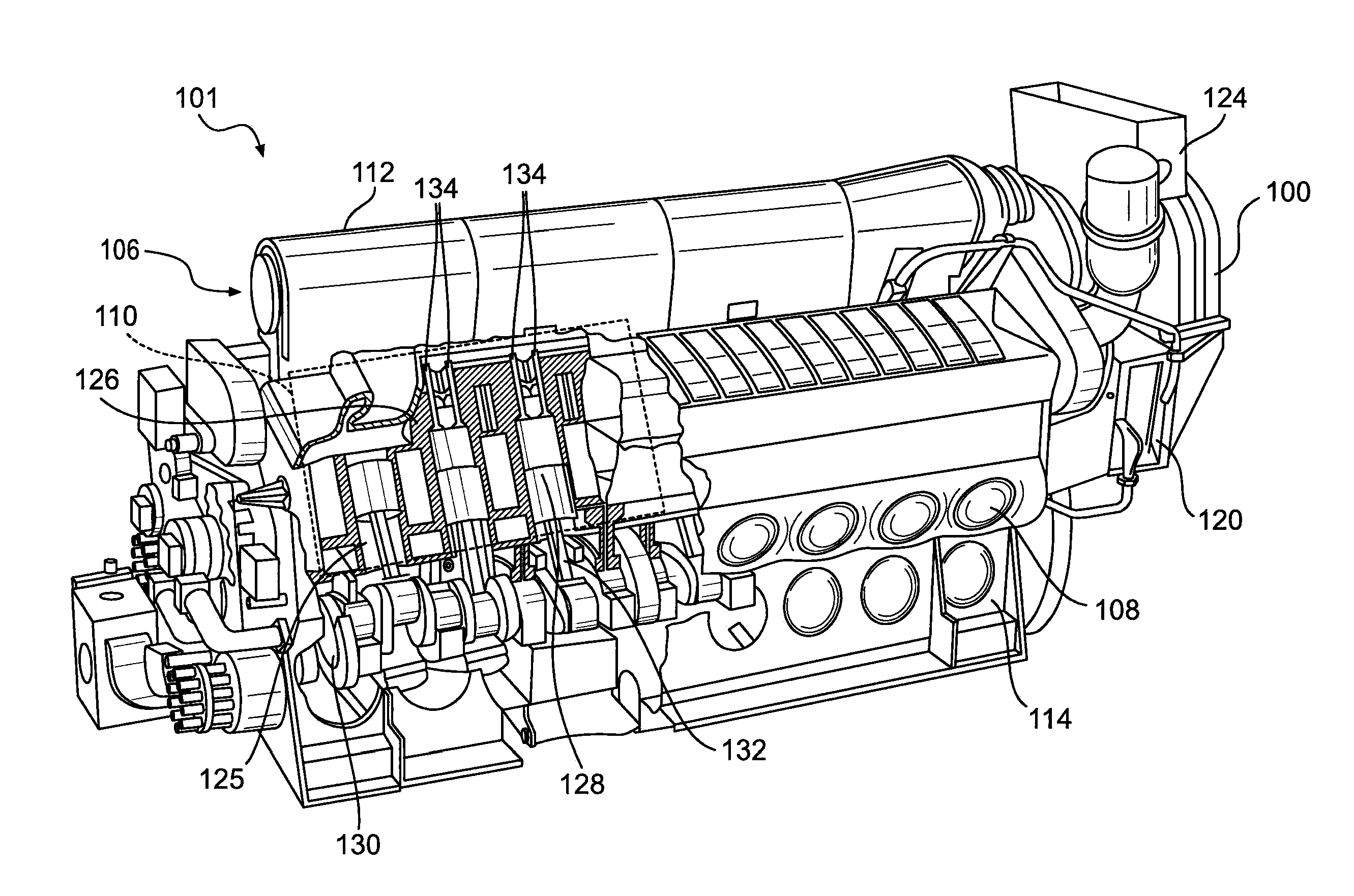
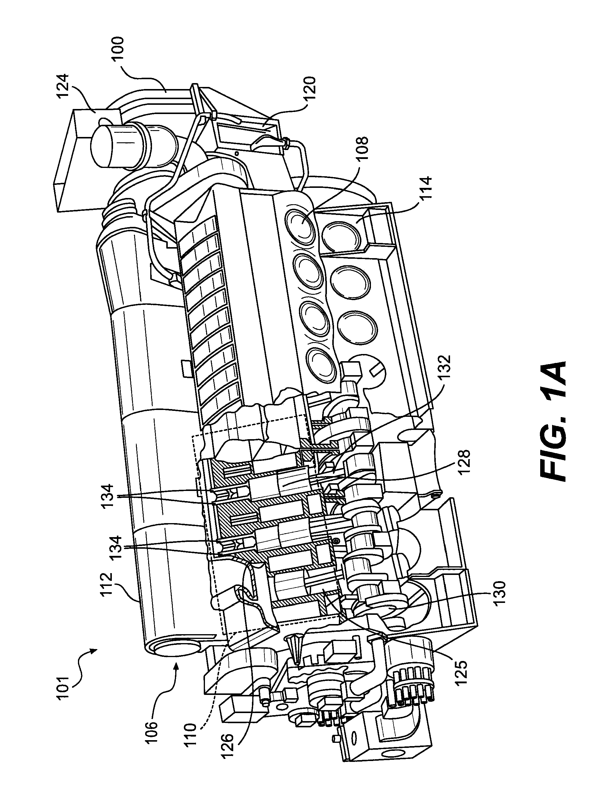
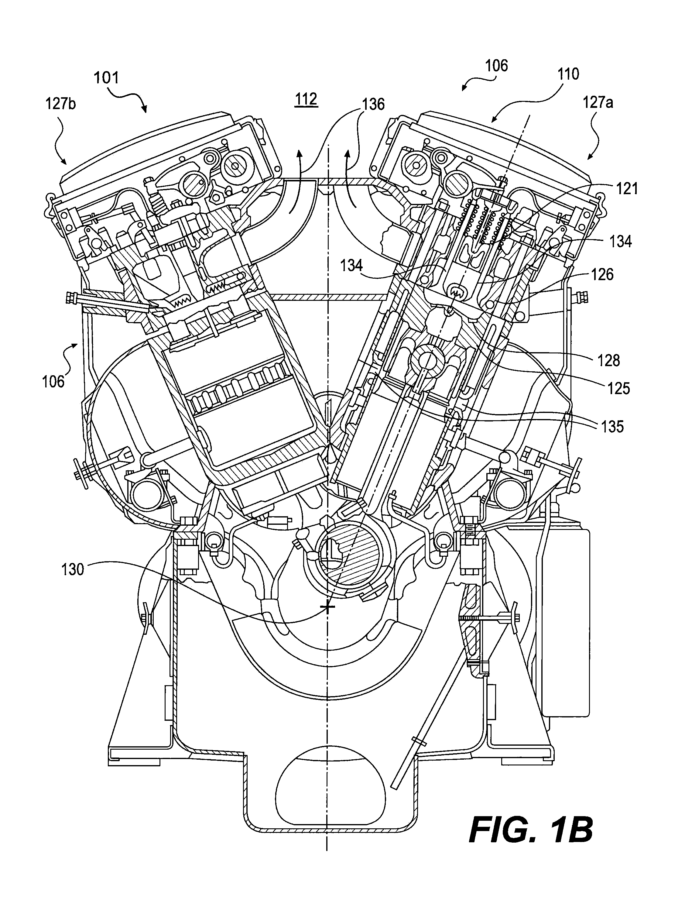
[0021]FIGS. 2A and 2B, schematically illustrate the presently disclosed exhaust emission reduction system including an engine system 201 including a turbocharger 200 having a compressor 202 for compressing air received from filter 218, and being driven by exhaust gases via turbine 204 in gas air / exhaust system 203. See FIG. 2A. Engine system 201 includes an engine 206 with two cylinder banks 227a, 227b, each having a plurality of cylinders 225 and associated pistons 228 reciprocable within the cylinders 225, as part of power assembly 210. The combustion cycle of a diesel engine includes, what is referred to as, scavenging and mixing processes. During the scavenging and mixing processes, a positive pressure gradient is maintained from airbox 208 through power assembly 210, and to the exhaust manifold 212 such that the cooled charge air from the airbox 208 charges the cylinders and scavenges most of the combusted gas from the previous combustion cycle. More specifically, during the sc...


PUM


Abstract

An exhaust emission reduction system for a fuel injected engine system has a plurality of emission reduction components configured to process the exhaust gas. The emissions reduction components include of one or more NOx reduction components and one or more filtration components configured to reduce particulate matter, hydrocarbons and/or carbon monoxide emissions. Each engine cylinder is associated with a respective one of the emission reduction components, such that exhaust gas from each engine cylinder flows through the respective one emission reduction component in parallel with the exhaust gas flows from the other cylinders through their respective emission reduction components.

Description

[0001]Applicants hereby claim priority to Provisional Application No. 61 / 502,610, filed Jun. 29, 2011, the entire content of which is hereby incorporated by reference.TECHNICAL FIELD[0002]The present disclosure relates generally to the field of exhaust emission reduction for internal combustion engines. More specifically, the present disclosure relates to systems for reducing one or more of particulate, hydrocarbon, carbon monoxide, and NOx exhaust emissions.BACKGROUND[0003]As depicted in FIGS. 1A-1C, in conventional turbocharged locomotive two-stroke diesel engine systems 101 having an air / exhaust system 103, the turbocharger 100 draws air from the atmosphere 116, which is filtered using a conventional air filter 118. The filtered air is compressed by a compressor 102. The compressor 102 is powered by a turbine 104, as will be discussed in further detail below. A larger portion of the compressed air (or “charge air”) is transferred to an aftercooler (or otherwise referred to as a h...

Claims


Application Information

Patent Timeline
IPC IPC(8): F01N3/035F02D41/30
CPCF01N3/035F02D41/0087F02D41/3058F01N3/103F01N13/0097F01N13/04F01N3/021F01N2590/08F01N13/017F01N3/2066
Inventor UZKAN, TEOMANGALLAGHER, THOMAS
Owner ELECTRO-MOTIVE DIESEL
Why Eureka
Try Eureka