Filter device
- Summary
- Abstract
- Description
- Claims
- Application Information
AI Technical Summary
Benefits of technology
Problems solved by technology
Method used
Image
Examples
first exemplary embodiment
[0055]Hereinafter, a filter device in accordance with a first exemplary embodiment of the present disclosure is described. In each exemplary embodiment, the same reference numerals are given to the same configurations as in preceding exemplary embodiments and detailed description thereof may be omitted. Furthermore, the present disclosure is not necessarily limited to the following exemplary embodiments.
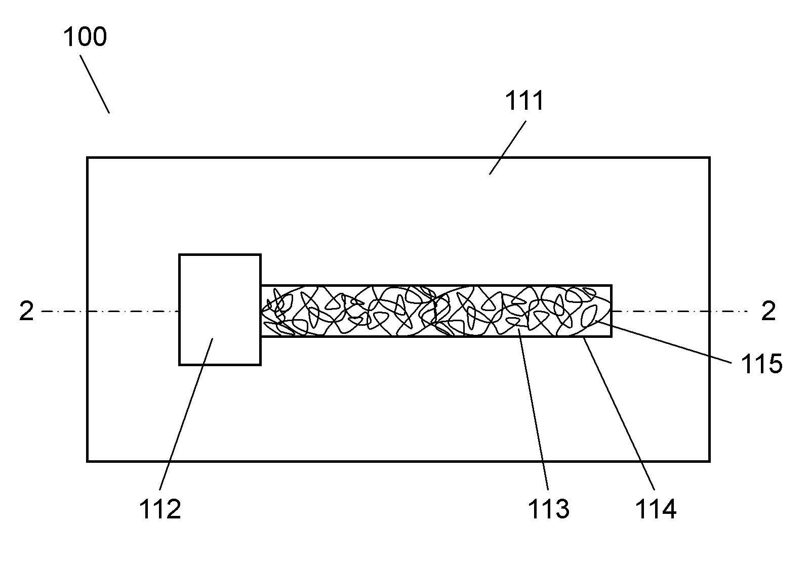
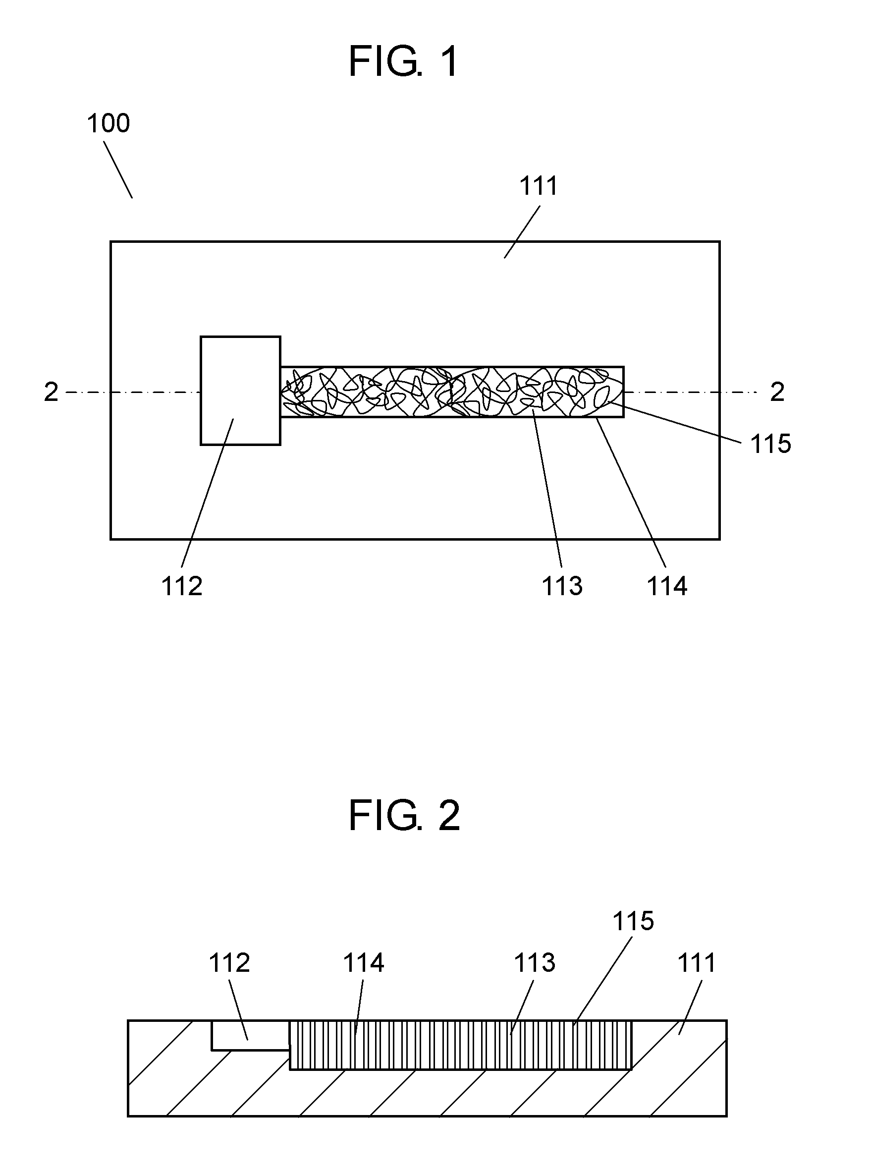
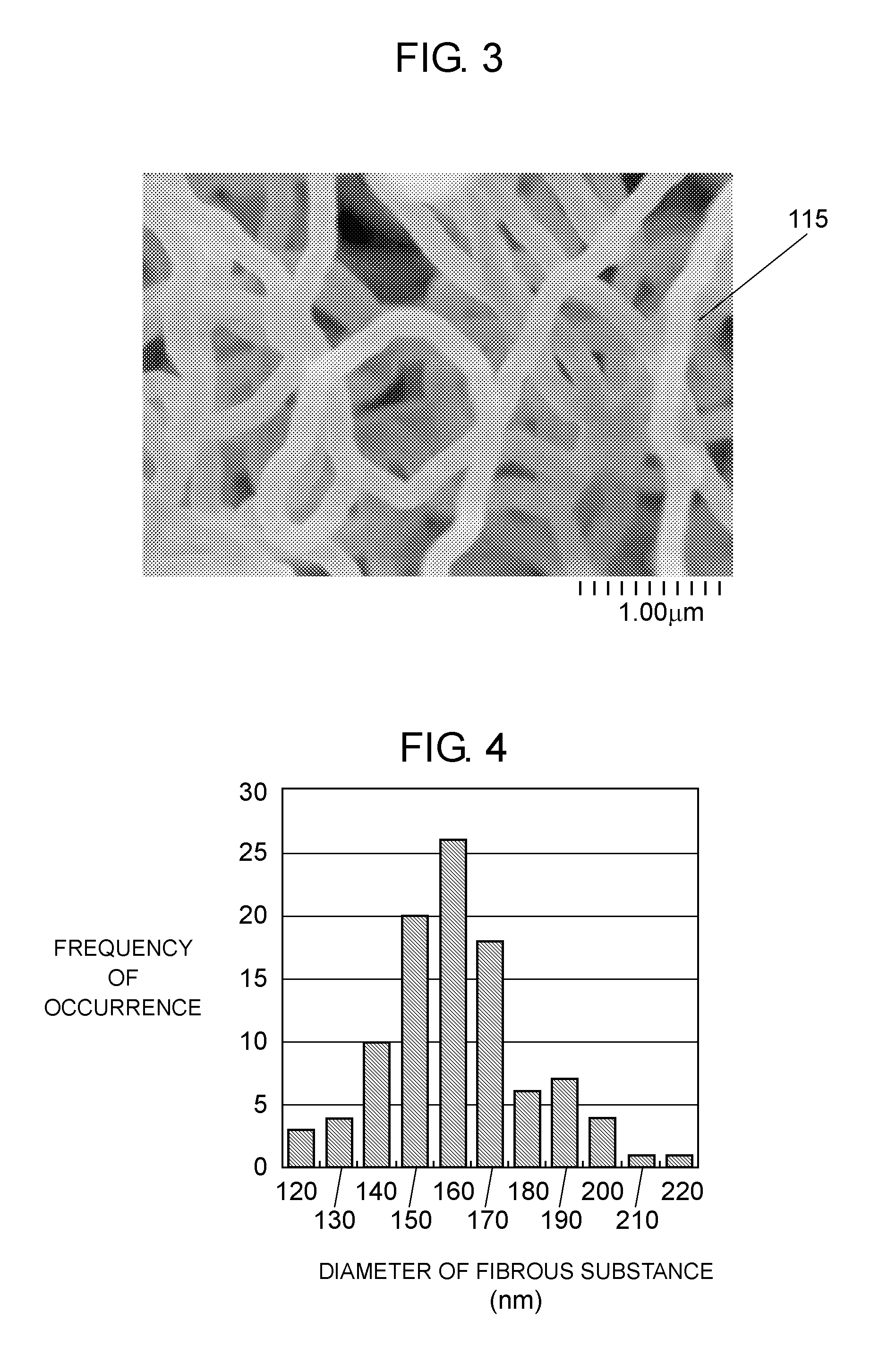
[0056]FIG. 1 is a top view of a filter device in accordance with this exemplary embodiment, FIG. 2 is a sectional view of the filter device taken on line 2-2 in FIG. 1, and FIG. 3 is an enlarged SEM photograph of a part of the filter device in accordance with this exemplary embodiment. As shown in FIG. 1, filter device 100 of this exemplary embodiment includes first port 112 and first flow passage 113. First port 112 is a port which is formed on substrate 111 and from which a solution containing a target substance is to be input. First flow passage 113 communicates with first port 11...
second exemplary embodiment
[0100]Hereinafter, a filter device of this exemplary embodiment is described with reference to drawings. Note here that description for the portions described in the first exemplary embodiment is omitted. This exemplary embodiment is different from the first exemplary embodiment in that second port 217 for extracting a specific substance is provided.
[0101]FIG. 10 is a top view of a filter device in accordance with this exemplary embodiment of the present disclosure. Filter device 200 of this exemplary embodiment includes second port 217. Second port 217 communicates with first flow passage 213 and extracts only a specimen from a solution. Furthermore, first flow passage 213 is provided with second flow passage 218. Second flow passage 218 is connected between first port 212 and second port 217. A buffer solution is allowed to flow from third port 219.
[0102]Second flow passage 218 can be provided by forming a flow channel on substrate 211 by fine processing such as an etching process...
third exemplary embodiment
[0111]Hereinafter, a filter device of this exemplary embodiment is described with reference to drawings. Note here that description for the portion described in the first exemplary embodiment is omitted. This exemplary embodiment is different from the first exemplary embodiment in that a filter chip having through holes is formed in a capillary.
[0112]FIG. 11 is a perspective view of a filter device in accordance with the third exemplary embodiment, and FIG. 12 is a sectional view thereof. As shown in FIG. 12, filter device 300 of this exemplary embodiment includes capillary 320 and filter chip 321. Filter chip 321 is provided at one end inside of capillary 320 such that a solution flowing in capillary 320 is brought into contact with filter chip 321. As shown in FIG. 12, filter chip 321 includes plate-like thin plate 322, and a plurality of through-holes 325. Through-holes 325 penetrate through first surface 323 and second surface 324 opposite to first surface 323 of thin plate 322....
PUM
| Property | Measurement | Unit |
|---|---|---|
| Fraction | aaaaa | aaaaa |
| Size | aaaaa | aaaaa |
| Size | aaaaa | aaaaa |
Abstract
Description
Claims
Application Information
 - R&D Engineer
- R&D Manager
- IP Professional
- Industry Leading Data Capabilities
- Powerful AI technology
- Patent DNA Extraction
Browse by: Latest US Patents, China's latest patents, Technical Efficacy Thesaurus, Application Domain, Technology Topic, Popular Technical Reports.
© 2024 PatSnap. All rights reserved.Legal|Privacy policy|Modern Slavery Act Transparency Statement|Sitemap|About US| Contact US: help@patsnap.com


