Scan-type image display device and scan-type projection device

a projection device and scan-type technology, applied in the direction of instruments, polarising elements, optical elements, etc., can solve the problems of large image distortion, large size of entire casing, and increased parts cost, and achieve the effects of small size, simple configuration, and large siz

Inactive Publication Date: 2013-01-03
HITACHI MEDIA ELECTORONICS CO LTD
View PDF15 Cites 11 Cited by
  • Summary
  • Abstract
  • Description
  • Claims
  • Application Information

AI Technical Summary

Benefits of technology

[0013]According to the present invention, it is possible to achieve a scan-type image display device and a scan-type projection devic

Problems solved by technology

It is known that in a scan-type image display device, distortion created in a displayed image lying on its screen depends on the angle of incidence of the light beam on the scanning mirror, and the image distortion becomes large in the case of beam incidence in the oblique direction.
A problem however arises in that increasing th

Method used


Image

  • Scan-type image display device and scan-type projection device
  • Scan-type image display device and scan-type projection device
  • Scan-type image display device and scan-type projection device

Examples


first embodiment

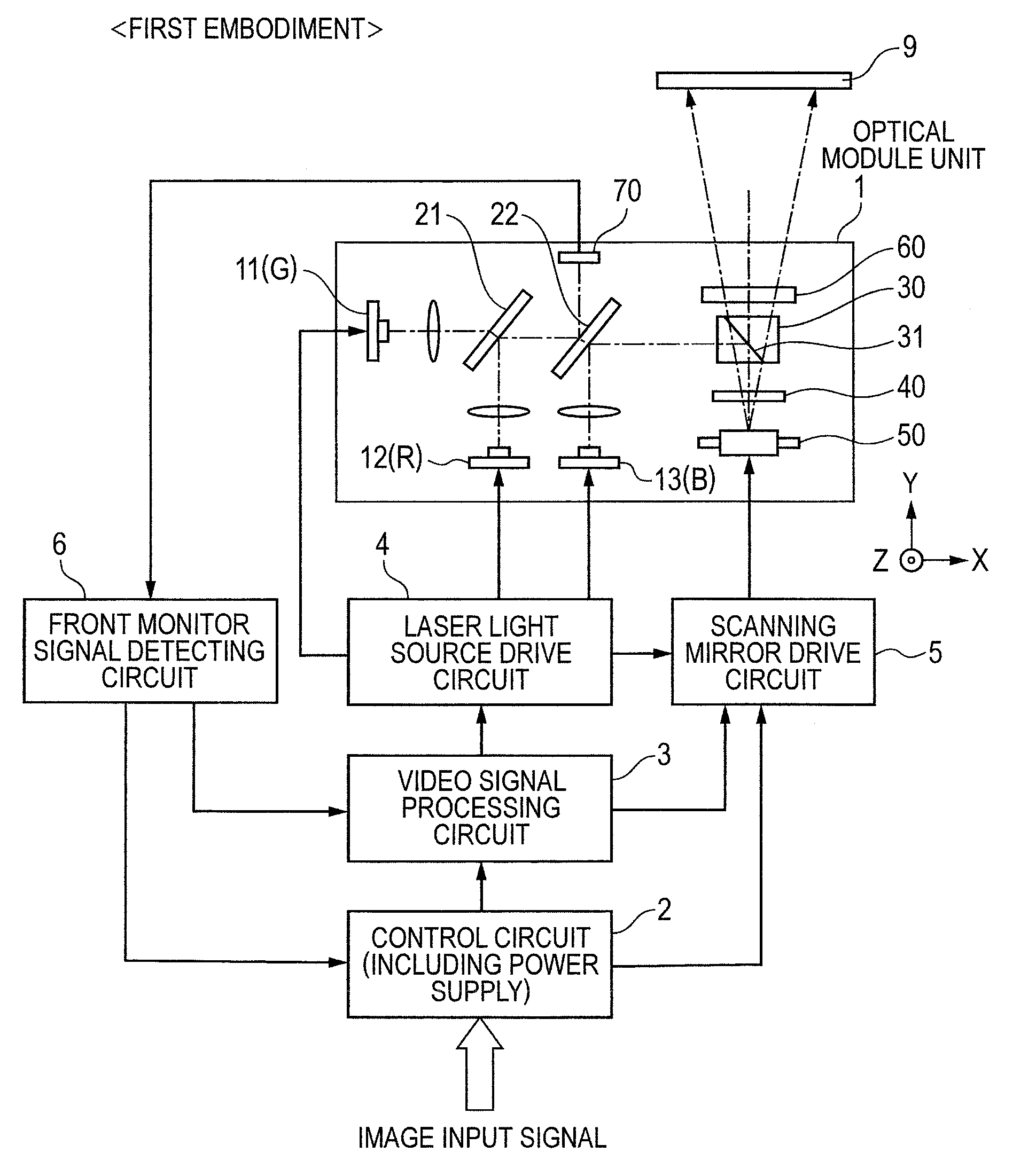
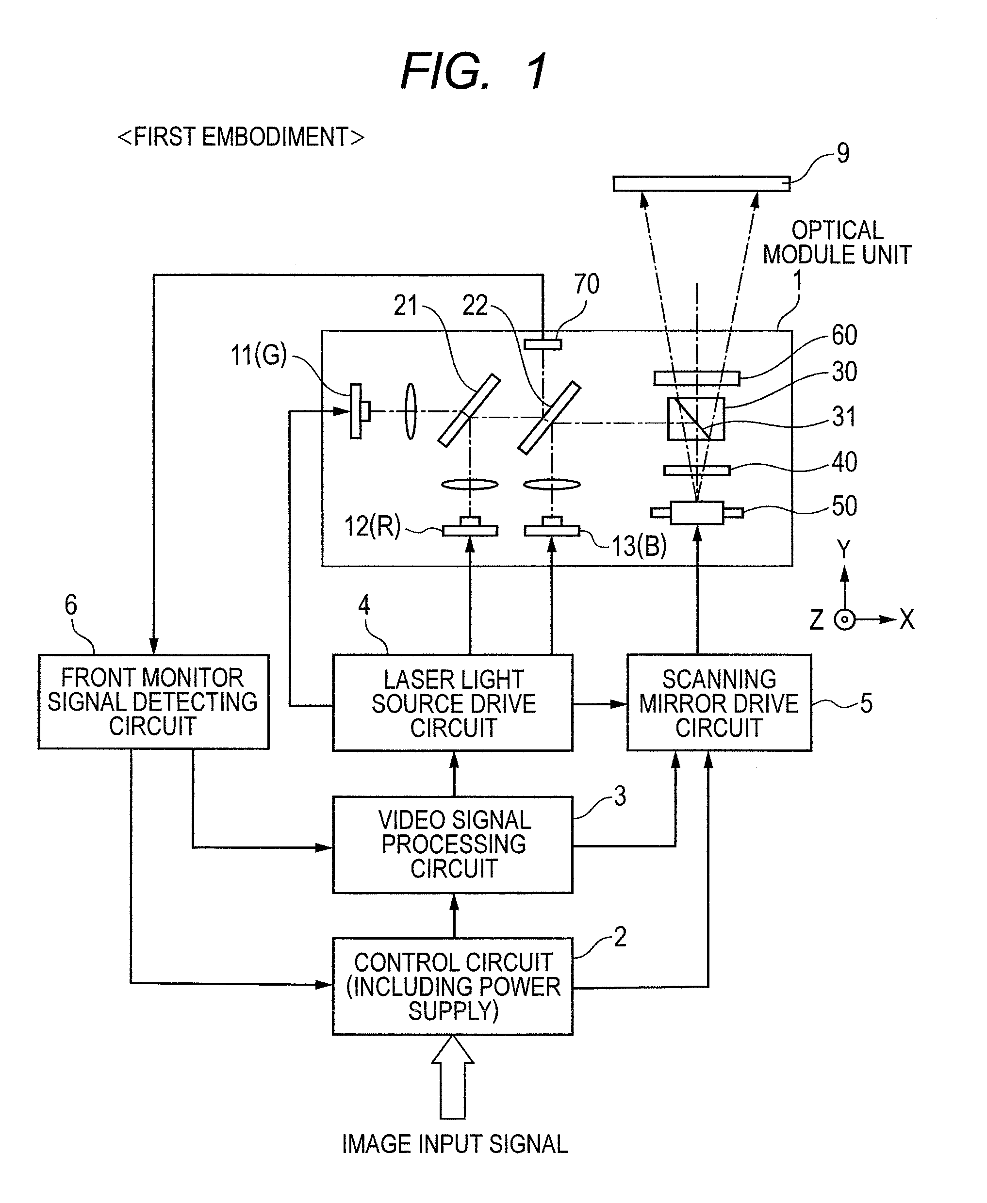
[0034]FIG. 1 is an overall configuration diagram showing a first embodiment of a scan-type image display device according to the present invention. A one-dot chain line in the drawing indicates an optical axis of each light beam. An optical module unit 1 has laser light sources 11, 12 and 13 of three colors of green (G) / red (R) / blue (B), an optical combination unit which combines light beams emitted from the laser light sources, a projection unit which projects the combined light beam onto a screen 9, and a scanning unit which two-dimensionally scans the projected light beam on the screen 9. The optical combination unit includes wavelength selective mirrors 21 and 22, etc. The projection unit includes a polarizing prism (polarizing beam splitter) 30 including a PBS (Polarizing Beam Splitter) film 31, a ¼ wave plate 40, a speckle reduction element 60, etc. The scanning unit includes a scanning mirror (deflecting mirror) 50, etc.

[0035]An image signal to be displayed is inputted to a v...

second embodiment

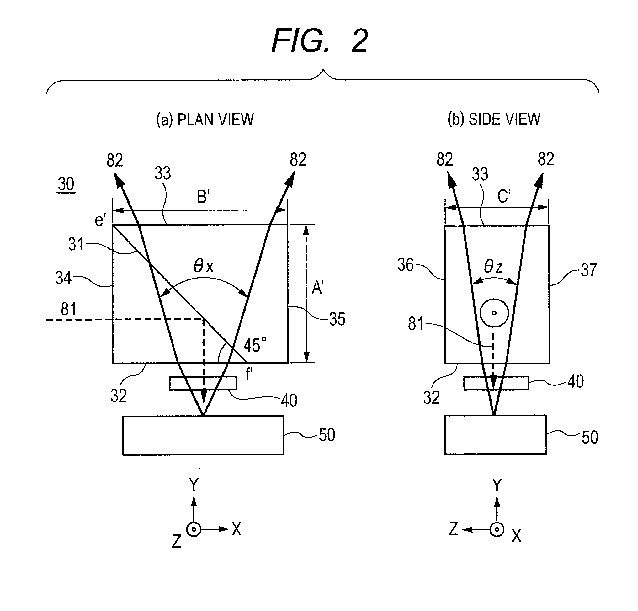
[0051]FIG. 3 shows the form of a second embodiment of a polarizing prism 30, in which FIG. 3(a) is a plan view thereof and FIG. 3(b) is a side view thereof. The present embodiment is a structure in which the polarizing prism of the first embodiment (FIG. 2) is further eliminated in plane. In the plan view (a), the first side plane 34 and the second side plane 35 of the polarizing prism 30 are obliquely cut in the traveling direction of each light beams 82. That is, the XY sectional shape becomes trapezoidal, and the dimension (width) B″ of the incident plane 32 is set smaller than the dimension (width) B′ of the outgoing plane and reduced to B″=5.5 mm. The PBS film 31 is placed in a plane that connects an angle f′ of the incident plane 32 and an angle e′ of the outgoing plane 33. At the mention of the XY sectional shape, one end of the PBS film 31 and the other end thereof are laid out so as to intersect with the short and long sides at an angle of approximately 45° assuming that a ...

third embodiment

[0053]FIG. 4 shows the form of a third embodiment of a polarizing prism 30, in which FIG. 4(a) is a plan view thereof and FIG. 4(b) is a side view thereof. The present embodiment is a structure in which the polarizing prism of the second embodiment (FIG. 3) is further removed in plane. In the side view (b), the upper plane 36 and the lower plane 37 of the polarizing prism 30 are obliquely cut in the traveling direction of the light beams 82. Thus, the dimension (height) C″ of the incident plane 32 is set smaller than the dimension (height) C′ of the outgoing plane 33 and reduced to C″=5 mm. In the present embodiment, the upper and lower planes of the polarizing prism 30 are obliquely cut to make it possible to provide a size reduction in the polarizing prism on a three-dimensional basis. Even in the present embodiment, the direction of the optical axis on the laser light source side is corrected to prevent the optical path in the polarizing prism 30 from varying.


PUM


Abstract

A polarizing prism is shaped in the form of a hexahedron. A polarizing beam splitter film (PBS film) is arranged approximately in a diagonal direction of the hexahedron. The polarizing prism holds a relationship of A<B when the dimension thereof in an outgoing direction (Y direction) of a light beam to a screen is A and the dimension thereof in an incident direction (X direction) of a light beam from a light source is B. For example, the polarizing prism is shaped in the form of a rectangular parallelepiped. At a plane on which the light beam is launched from a scanning mirror, one end of the PBS film is placed so as to intersect with the incident plane at an angle of approximately 45° at a position deviated inside by a difference between the dimensions A and B from the end of the incident plane.

Description

CLAIM OF PRIORITY[0001]The present application claims priority from Japanese patent applications serial no. JP 2011-147275, filed on Jul. 1, 2011, no. JP 2011-156260, filed on Jul. 15, 2011, and no. JP 2011-270403, filed on Dec. 9, 2011, the contents of which are hereby incorporated by reference into this application.BACKGROUND OF THE INVENTION[0002](1) Field of the Invention[0003]The present invention relates to a scan-type image display device and a scan-type projection device each of which two-dimensionally scans a light beam by a scanning mirror and displays an image on a screen.[0004](2) Description of the Related Art[0005]A scan-type image display device and a scan-type projection device have recently been realized which respectively two-dimensionally scan a light beam emitted from a semiconductor laser light source on a screen by means of a scanning mirror (deflection mirror) and display an image thereon. There has been described in, for example, JP-A-2006-189573 and JP-T-200...

Claims


Application Information

Patent Timeline
IPC IPC(8): G03B21/14G02B26/10
CPCG02B26/108H04N9/3173H04N9/3167H04N9/3129
Inventor TANAKA, TEPPEINAKAO, TAKESHISUGIYAMA, MASATOHATAGI, MICHIOKAWAMURA, TOMOTOKITA, HIROMIOHNISHI, KUNIKAZU
Owner HITACHI MEDIA ELECTORONICS CO LTD
Why Eureka
Try Eureka