Resin molded body

a technology of molded body and resin, applied in the direction of optical radiation measurement, instruments, spectrometry/spectrophotometry/monochromators, etc., can solve the problems of narrow angle range in which structural colors are observable, and inability to obtain sufficient structural color effects, etc., to achieve the effect of convenient fabrication

Active Publication Date: 2013-01-03
HAMAMATSU PHOTONICS KK
View PDF0 Cites 27 Cited by
  • Summary
  • Abstract
  • Description
  • Claims
  • Application Information

AI Technical Summary

Benefits of technology

[0015]The present invention solves the above-described problem, and an object thereof is to provide a resin molded body that develops structural colors and can widen an angle range in which the structural colors are observable.
[0017]On a principal surface of a structural color body having lamellar micro domains oriented parallel to the principal surface, the incident angle range that satisfies the Bragg reflection condition tends to become narrow, so that a structural color tends to become harder to observe when light in the visible light range is made incident on the principal surface from a direction inclined with respect to the thickness direction of the structural color body. On the other hand, in the resin molded body according to the present invention, the first resin layer has a micro-phase separated structure including lamellar micro domains, so that the resin molded body can develop structural colors as a structural color body. In the resin molded body, each of the micro domains of the first resin layer has a wave-like shape having amplitudes in the opposite direction, and in each of the micro domains of the first resin layer, a maximum value of distances in the opposite direction between the tops of convexities and the bottoms of concavities of the micro domain is larger than the wavelength in the visible light range. In this case, even when light in the visible light range is made incident on the principal surface of the resin molded body from a direction inclined with respect to the opposite direction, a region perpendicular to an incident direction of light and a region inclined with respect to an incident direction of light to an extent to satisfy the Bragg reflection condition easily exist in the micro domains of the first resin layer, so that light can be reflected at these regions. Therefore, in the above-described resin molded body, even when light in the visible light range is made incident on the principal surface of the resin molded body from a direction inclined with respect to the opposite direction, light reflected at the first resin layer can be observed as a structural color, so that an angle range in which structural colors are observable can be widened.
[0028]The thickness in the opposite direction of the resin molded body is preferably more than 1000 μm and not more than 3000 μm. In this case, an angle range in which structural colors are observable can be easily widened.
[0029]The resin molded body according to the present invention develops structural colors and can widen an angle range (inclined angle range with respect to the opposite direction of the principal surfaces of the resin molded body) in which the structural colors are observable. The resin molded body according to the present invention can be easily fabricated without requiring a complicated step such as vacuum semiconductor process.

Problems solved by technology

Therefore, in a case where a resin molded body having a lamellar micro-phase separated structure is fabricated, when light in the visible light range is made incident on a principal surface of the structural color body having lamellar micro domains oriented parallel to the principal surface of the resin molded body, an angle range in which structural colors are observable tends to become narrow, and a sufficient structural color effect cannot be obtained.

Method used


Image

  • Resin molded body
  • Resin molded body
  • Resin molded body

Examples


first embodiment

Resin Molded Body

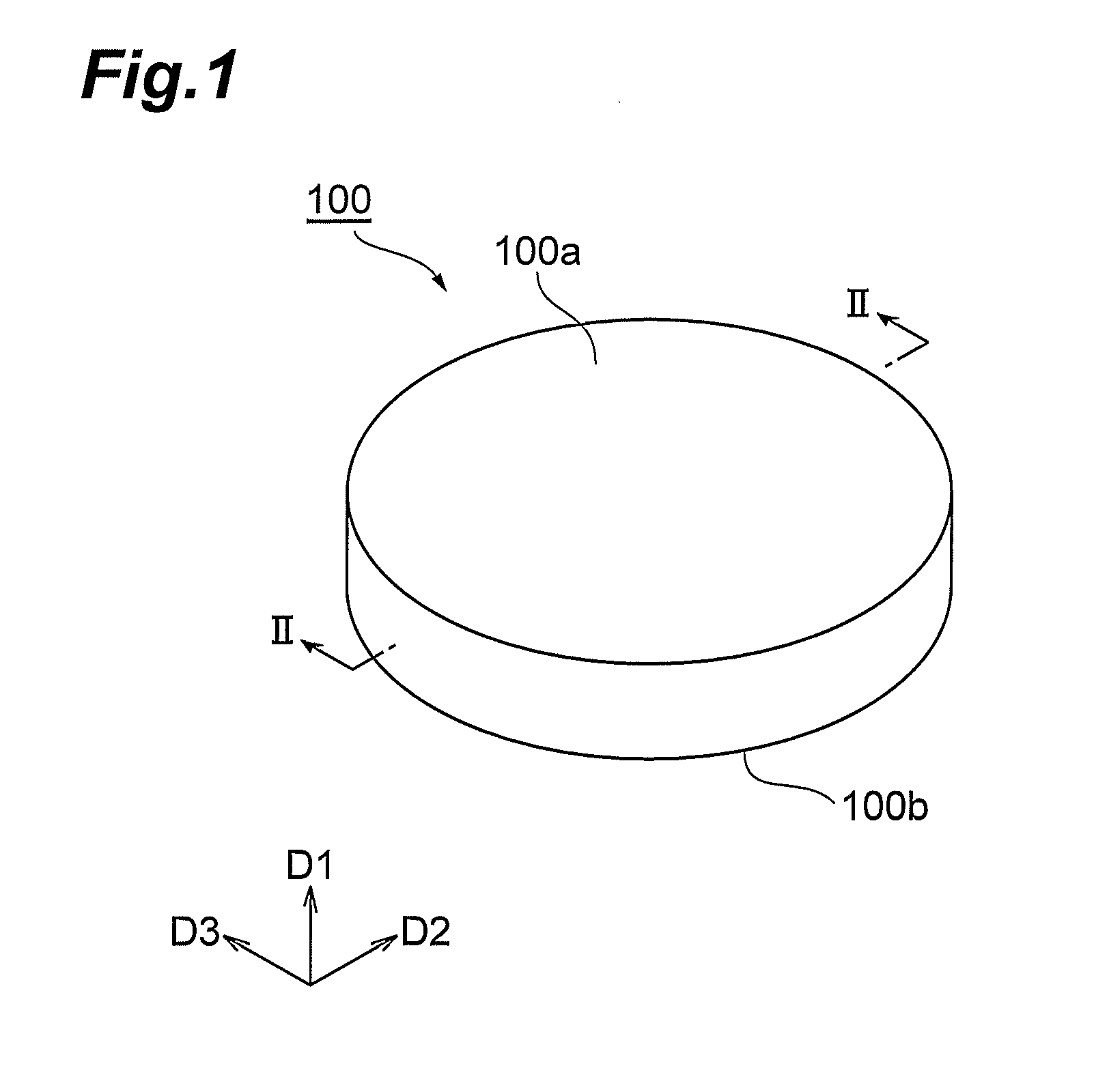
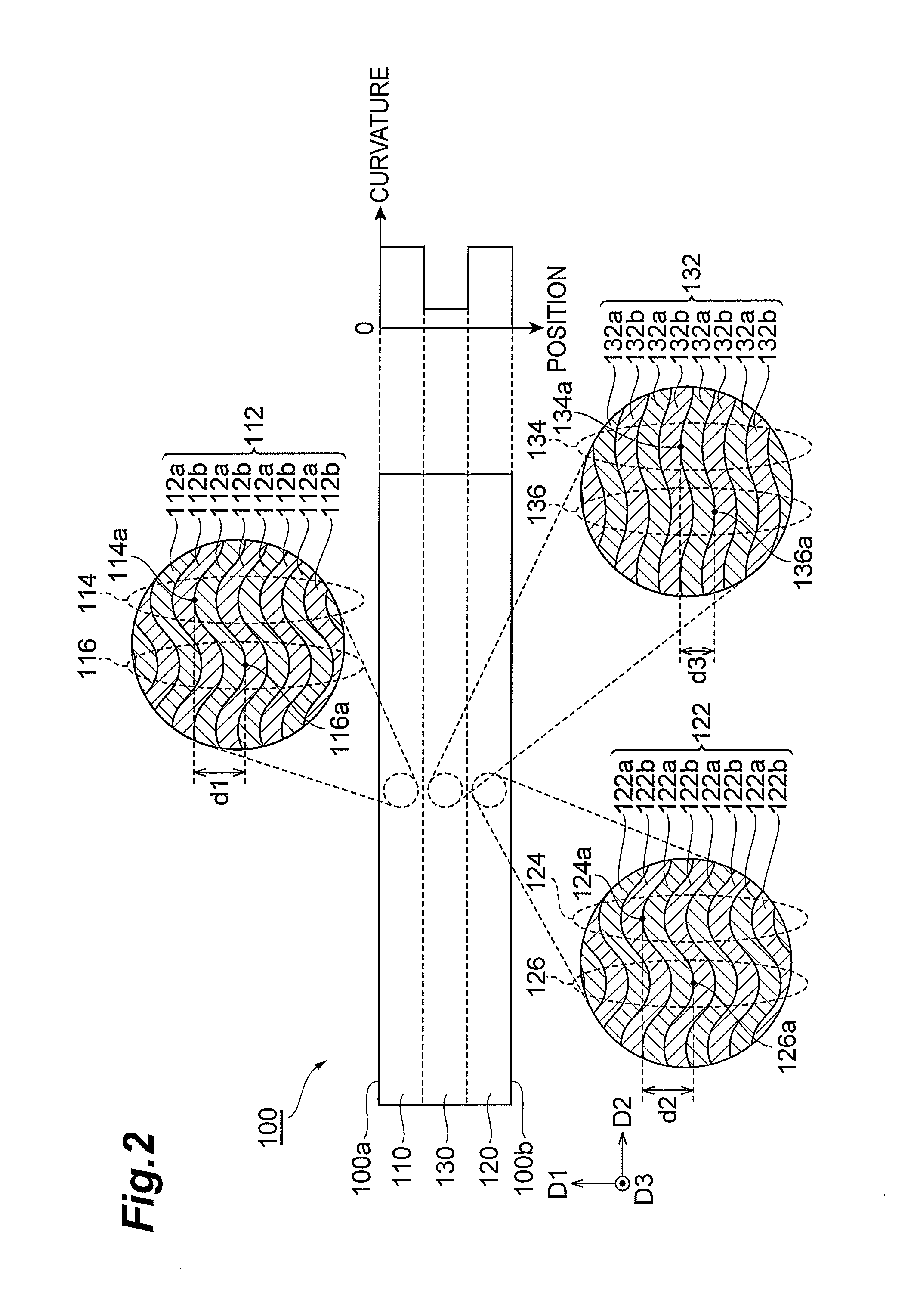
[0044]FIG. 1 is a perspective view showing a resin molded body according to a first embodiment. FIG. 2 is a schematic sectional view taken along line II-II in FIG. 1. The resin molded body (structural color body) 100 according to the first embodiment is, for example, cylindrical, and has a front surface (first principal surface) 100a and a back surface (second principal surface) 100b opposed substantially parallel to each other. The thickness of the resin molded body 100 in the opposite direction D1 of the front surface 100a and the back surface 100b is preferably more than 1000 μM and not more than 3000 μm.

[0045]The resin molded body 100 comprises a front surface layer (first resin layer) 110 disposed on the front surface 100a side, a back surface layer (second resin layer) 120 disposed on the back surface 100b side, and an intermediate layer (third resin layer) 130 disposed between the front surface layer 110 and the back surface layer 120. The resin molded body 1...

second embodiment

Resin Molded Body

[0092]FIG. 8 is a schematic sectional view showing a resin molded body according to a second embodiment. A resin molded body (structural color body) 150 according to the second embodiment has the same configuration as that of the resin molded body 100 according to the first embodiment except that the resin molded body 150 comprises an intermediate layer (third resin layer) 140 instead of the intermediate layer 130.

[0093]The resin molded body 150 is, for example, cylindrical, and has a front surface (first principal surface) 150a and a back surface (second principal surface) 150b opposed substantially parallel to each other.

[0094]The thickness of the resin molded body 150 in the opposite direction D1 of the front surface 150a and the back surface 150b is preferably more than 1000 μm and not more than 3000 μm.

[0095]The intermediate layer 140 is in contact with the front surface layer 110 and the back surface layer 120 between the front surface layer 110 and the back s...

third embodiment

Resin Molded Body

[0110]FIG. 10 is a schematic sectional view showing a resin molded body according to a third embodiment. The resin molded body (structural color body) 200 according to the third embodiment is, for example, cylindrical, and has a front surface (first principal surface) 200a and a back surface (second principal surface) 200b opposed substantially parallel to each other. The thickness of the resin molded body 200 is preferably more than 1000 μm and not more than 3000 μm.

[0111]The resin molded body 200 comprises a front surface layer (first resin layer) 210 disposed on the front surface 200a side and a back surface layer (second resin layer) 220 disposed on the back surface 200b side. The resin molded body 200 is formed by laminating the back surface layer 220 and the front surface layer 210 in this order. The back surface layer 220 is in contact with the front surface layer 210.

[0112]The thickness of the front surface layer 210 is preferably 300 to 1000 μm. The thickne...


PUM

PropertyMeasurementUnit
thicknessaaaaaaaaaa
thicknessaaaaaaaaaa
refractive indexaaaaaaaaaa

Abstract

A resin molded body comprises a front surface layer disposed on a front surface side, a back surface layer disposed on a back surface side, and an intermediate layer disposed between the front surface layer and the back surface layer, each of the layers has a micro-phase separated structure including lamellar micro domains, each of the micro domains of the layers has a wave-like shape having amplitudes in the opposite direction of the front surface and the back surface, a maximum value of predetermined distances in the micro domains of the front surface layer and a maximum value of predetermined distances in the micro domains of the back surface layer are larger than the wavelength in the visible light range, and predetermined distances in the micro domains of the intermediate layer are equal to or less than the wavelength in the visible light range.

Description

BACKGROUND OF THE INVENTION[0001]1. Field of the Invention[0002]The present invention relates to a resin molded body, and particularly, to a resin molded body that develops structural colors.[0003]2. Related Background Art[0004]As a resin molded body that develops structural colors, a structural color body is a color body that develops structural colors, and causes phenomena such as reflection, interference, refraction, diffraction and scattering of light due to the microstructure of the color body to develop lights inherent to the microstructure. As a structural color body, a structural body (for example, refer to Patent Documents 1 to 3 listed below) obtained by laminating films with refractive indexes different from each other on a surface with concavities and convexities of a substrate, and a multilayer film (for example, refer to Non-Patent Document 1 listed below) having a curved shape have been proposed.[0005]As a structural color material for forming the structural color bod...

Claims


Application Information

Patent Timeline
Patent Type & Authority Applications(United States)
IPC IPC(8): B32B3/30
CPCC08J5/00C08J2353/00C08L53/00B32B27/08B32B3/28Y10T428/269Y10T428/24521Y10T428/2495Y10T428/18Y10T428/24529Y10T428/261G03F7/0002Y10T428/249921Y10T428/249994
Inventor HARA, SHIGEOYAMANAKA, TAKAHIKO
Owner HAMAMATSU PHOTONICS KK
Why Eureka
Try Eureka