Mr-angiography with non-cartesian signal acquisition

a signal acquisition and angiography technology, applied in the field of angiography with non-cartesian signal acquisition, can solve the problems of tr, more striking limitation, and significantly shorter distance traveled by the blood during the remaining weak pulse wave, and achieve good spatial resolution

Active Publication Date: 2013-01-03
SIEMENS HEALTHCARE GMBH
View PDF8 Cites 12 Cited by
  • Summary
  • Abstract
  • Description
  • Claims
  • Application Information

AI Technical Summary

Benefits of technology

[0008]It is an object of the present invention to provide an angiography method that enables a good spatial resolution along all three spatial axes, without significantly lengthening the measuring time period.
[0013]Individual spokes of the radial trajectory can be designed, for example, such that a plane is produced in raw data space at a right angle to the main flow direction, with the spokes irregularly distributed in this plane such that, at a right angle to the flow of blood, an elliptical or oval field of view is obtained in the MR angiographic image, instead of a circular field of view. As a result of the irregular density of the radial spokes, an elliptical or oval field of view can be obtained in the image space, which enables an optimized adjustment of the signal recording to the object that is to be depicted. This is the case, above all, in the leg and abdominal region, where approx. 35-45 cm is to be covered in the left-right direction, while in the anterior-posterior direction, only 15-25 cm needs to be covered.
[0014]Preferably, prior to the signal recording for the creation of the MR angiographic image, a sequence module is executed for suppressing the fat signal during the signal recording. To the greatest extent possible, only the image points of the blood vessels should generate bright image points in the MR angiography. The fat signal also produces bright image points during the imaging. Through the suppression of the fat signal, it is possible to suppress high signal portions of potential fatty tissues in the MR angiographic image and to limit the bright signal points to the vessels.
[0025]In another embodiment, it is possible to allow the density of the spokes to decrease in the individual partitions from the center of the cylindrically shaped raw data space towards the edge along the plane of the partition. With this embodiment, the density, or number of spokes in the three-dimensional cylindrical k-space decreases with the increasing spacing of the partition encoding plane from the plane kz=0, wherein the z-axis in turn is the main flow direction, without limiting the generality, and the individual partitions are perpendicular to said z-axis.

Problems solved by technology

A fundamental problem with this method is that the vessels of the volume in question must be filled during tin with fresh blood, flowing in from outside of the marked volume.
This limitation is more striking with patients whose pulsatile dynamics are less pronounced, wherein the distance traveled by the blood during the remaining weak pulse wave may be significantly shorter.
To create thinner thicknesses, an extension of the RF pulse, and thus the repetition periods TR, is required, which is undesired.
Furthermore, with even thinner layers, the obtainable signal-to-noise ratio is marginally low, in particular with the clinically, currently most commonly used, field strengths of 1.5 tesla.
This spatial resolution, limited in the z-axis, represents a major limitation of the method, in particular when finer vessels do not run strictly along the z-axis, as is the case, for example, in regions of the trifurcation in the lower leg, or with pathologies.
A problem with this alternative would be that efficiency would not be increased because the time for encoding a 3D partition is the same as that for the acquisition of a 2D layer.
This is a problem, because, for example, with an angiography of the pelvis-leg region, normally a coverage from the feet up to the abdominal region is desired.

Method used


Image

  • Mr-angiography with non-cartesian signal acquisition
  • Mr-angiography with non-cartesian signal acquisition
  • Mr-angiography with non-cartesian signal acquisition

Examples


Embodiment Construction

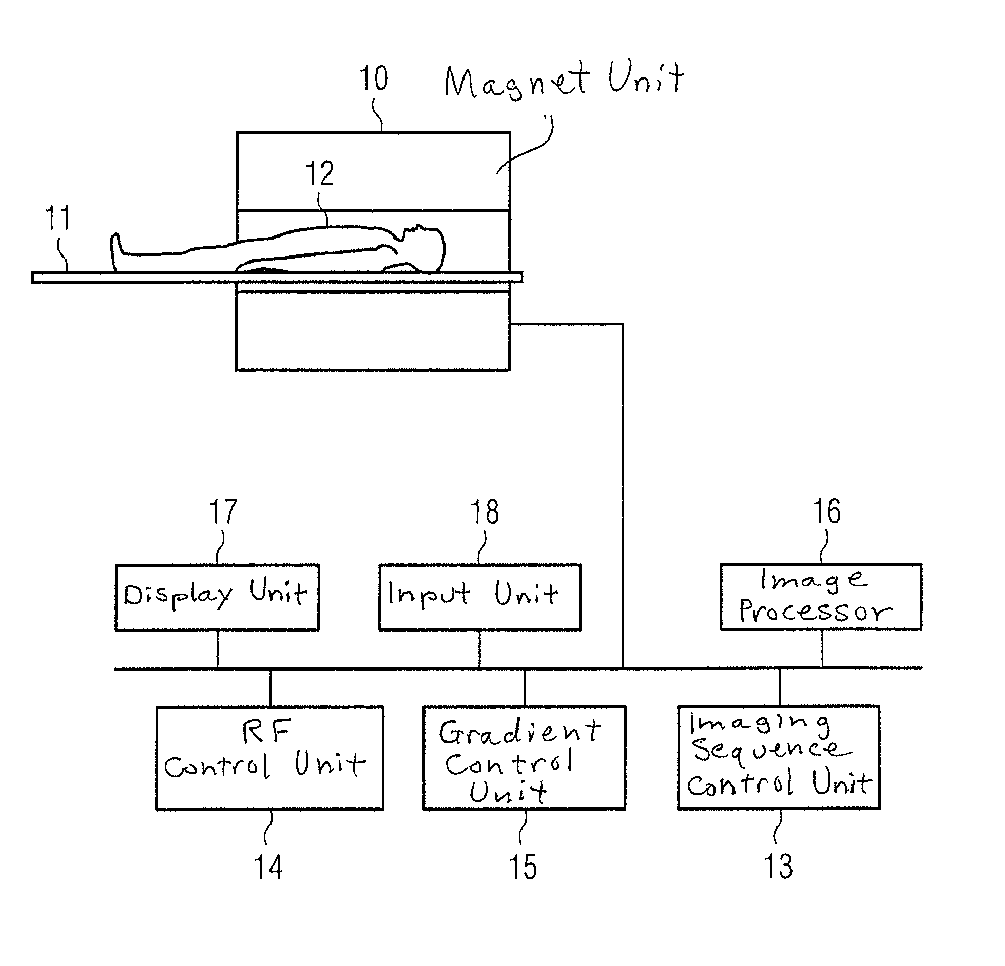
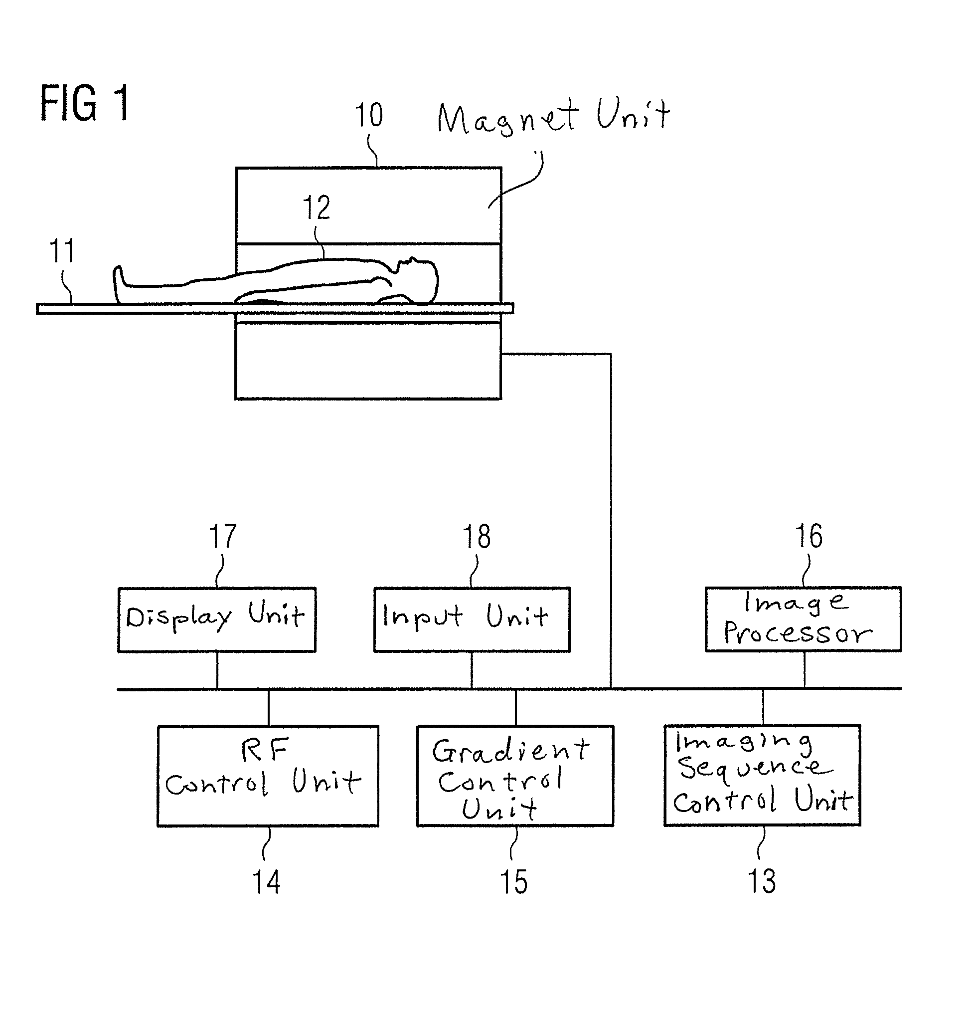
[0034]An MR apparatus is depicted schematically in FIG. 1, with which an MR angiographic image having a good spatial resolution in all three spatial planes can be created in an acceptable measurement time period. The MR apparatus has a magnet 10 for generating a polarization field BO. An examination subject 12 placed on a bed 11 is moved into the magnet 10. The magnetization present in the examination subject can be tipped out of equilibrium by irradiating the patient with radio-frequency pulses. The relaxation processes occurring after the irradiation with RF pulses can be detected by coils, not shown in FIG. 1. For the spatial encoding of the detected signals, magnetic field gradients are superimposed on the basic magnetic field by gradient coils (not shown) in order to obtain a spatial connection of the detected signals. The method in general, with which MR images can be generated by means of a sequence of emitted RF pulses, and the activation of magnetic field gradients, is know...


PUM


Abstract

In a method and apparatus for the creation of an MR image of a vascular structure of an examination region, the spins in the examination region are saturated by the irradiation of at least one RF saturation signal, which delivers a lower signal intensity as spins in a subsequent MR signal recording for the creation of the MR angiographic image, which flow through at least one blood vessel into the examination region, and are not saturated by the RF saturation pulse. Raw data space of the MR angiographic image is read out with a non-Cartesian trajectory in the MR signal acquisition for the creation of the MR angiographic image.

Description

BACKGROUND OF THE INVENTION[0001]1. Field of the Invention[0002]The present invention concerns a method for the generation of an MR image of a vascular structure of an examination region, and an MR apparatus for this purpose. In the following, the term “angiography image” shall be used in the generic sense; it does not necessarily encompass only a single two-dimensional image, but depending on the context, may also encompass an angiographic image data set of a desired volume.[0003]2. Description of the Prior Art[0004]In the field of MR angiography, methods that function without the need for contrast agents are gaining significance. One class of such methods exploits the pulsatile nature of the arterial blood flow. With signal recording (data acquisition) of a flow-sensitive sequence at the point in time of the quicker flow rate (systole), one obtains, in the ideal case, a deletion (absence) of the arterial signal. With a signal recording at the point in time in the cardiac cycle at ...

Claims


Application Information

Patent Timeline
Patent Type & Authority Applications(United States)
IPC IPC(8): A61B5/055
CPCG01R33/5635G01R33/4824
Inventor SCHMITT, PETER
Owner SIEMENS HEALTHCARE GMBH
Why Eureka
Try Eureka