Device and method for heat pump based clothes dryer

a technology of heat pump and clothes dryer, which is applied in the direction of washing machines with receptacles, lighting and heating apparatus, furnaces, etc., can solve the problems of limited drying capacity, long drying cycle times, and dehumidification of air prior to drying, and achieve the effect of efficient use of enthalpy

Active Publication Date: 2013-01-10
HAIER US APPLIANCE SOLUTIONS INC
View PDF7 Cites 55 Cited by
  • Summary
  • Abstract
  • Description
  • Claims
  • Application Information

AI Technical Summary

Benefits of technology

[0014]A controller may be provided for controlling the heat pump based dryer and may be associated with at least one sensor for measuring at least one variable output. The controller is configured to receive and process data representative of sensor readings measured by the sensor for selectively maintaining at least a temperature of the fluid to be below a dew point of the air at the outlet of the housing. The controller may also be configured to manipulate the outputs of a f

Problems solved by technology

Additionally, it is known to introduce a continuous flow of cold water to the warm humid air to cause dehumidification of the air prior to being vented to the atmosphere.
These dryers often have a very limited drying capacity and also have longer drying cycle times. These dryers also consume large amounts of energy and water during the drying process.
In some designs, cold water is used in the heat exchanger, eliminating this heating, but also requiring increased water usage.
As a consequence of the increased humidity of the air used to dry the load, this type of dryer requires relatively more time than the conventional dryer.
With respect to ambient air, the higher humidity of the air u

Method used


Image

  • Device and method for heat pump based clothes dryer
  • Device and method for heat pump based clothes dryer
  • Device and method for heat pump based clothes dryer

Examples


Embodiment Construction

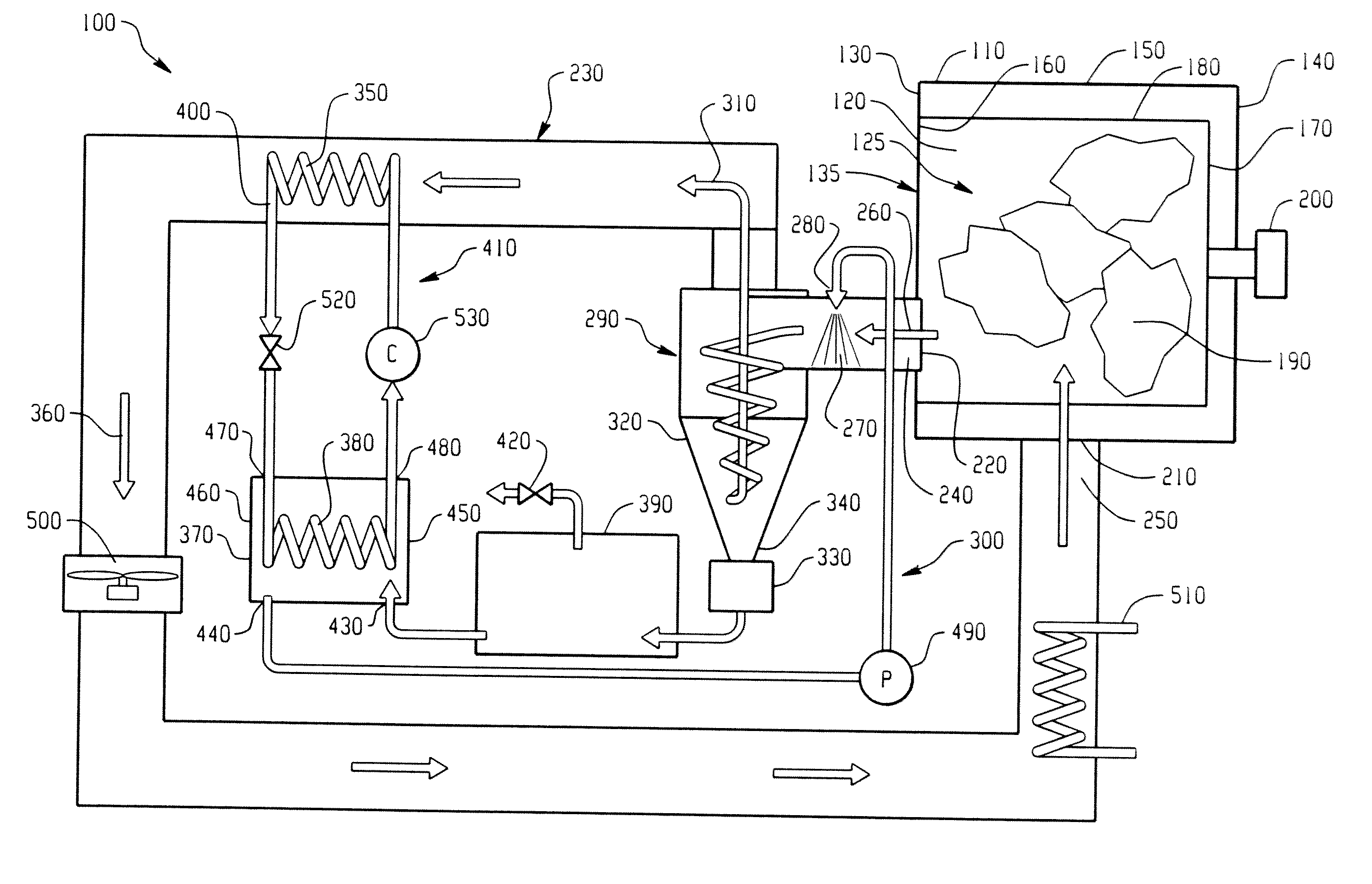
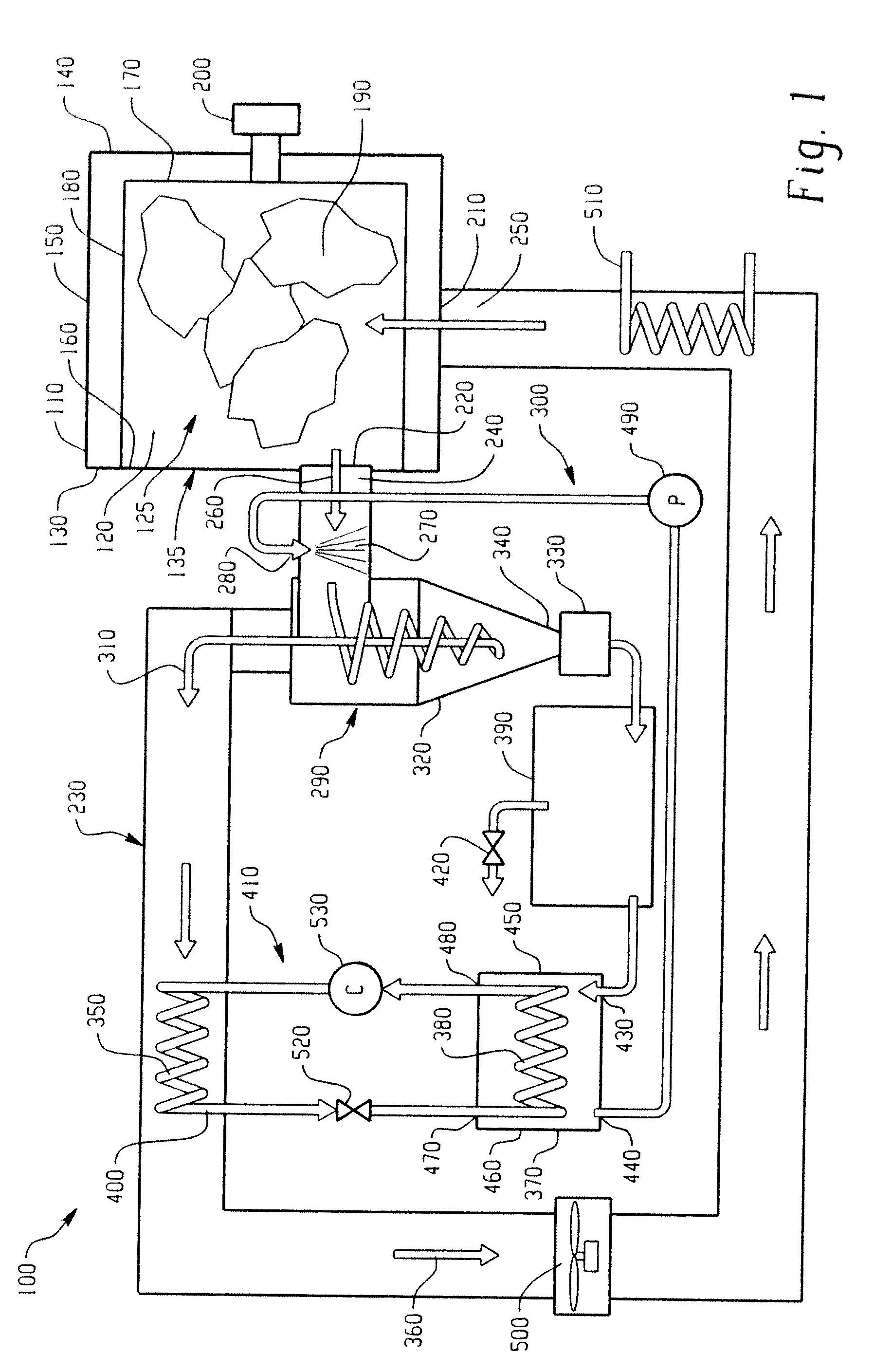
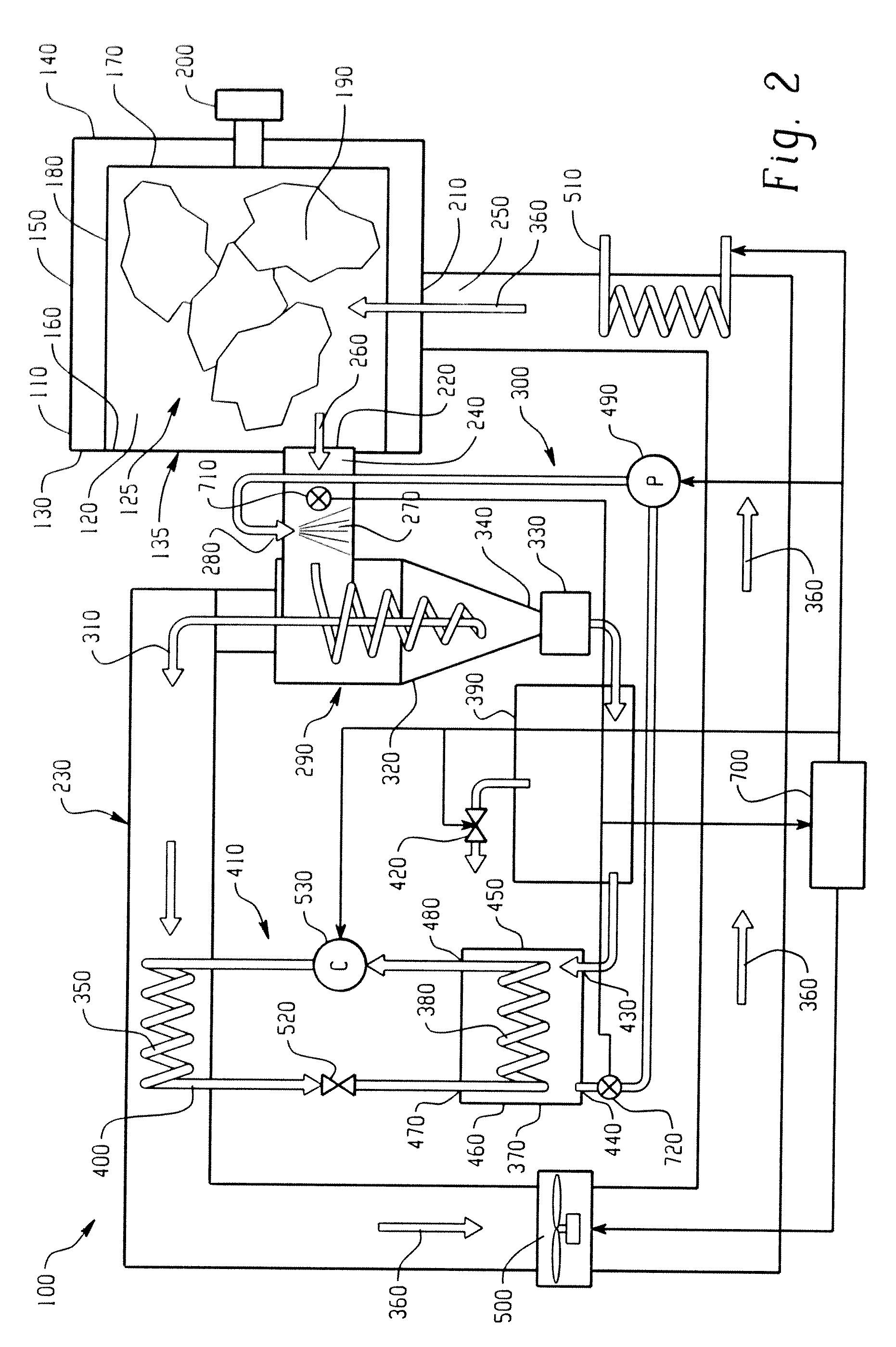
[0024]The present disclosure is generally directed to a heat pump dryer and a method of drying articles with a heat pump based dryer that provide a more concise, efficient, and cost effective device and method for reducing energy consumption in a heat pump dryer by using the enthalpy of a circulating fluid, an evaporator, and air within the device. This dryer and method are directed at a home appliance for drying moist clothing articles. This dryer may include an individual dryer appliance or may comprise a combination washer / dryer appliance having a washing cycle prior to a drying cycle.

[0025]FIGS. 1-5 depict a schematic layout of various embodiments of the heat pump dryer 100. The dryer 100 preferably comprises a housing 110 for receiving and enclosing a drum 120 having a cavity 125 therein. The housing 110 has a first end 130, a second end 140 and at least one side 150 extending generally perpendicularly between the first and second ends 130, 140. The first end 130 includes an ac...


PUM


Abstract

The present disclosure relates to a heat pump based dryer or a combination washer and dryer device comprising a housing receiving a drum for containing associated articles to be dried by air that flows along a pathway between an outlet and an inlet of the housing. A fluid is provided in the pathway to at least partially remove moisture from the air. A heat pump includes a heat source located at least partially within the pathway and a heat sink being operatively adapted to the heat source to circulate a refrigerant therein. An enclosure at least partially containing the heat sink is arranged to accept the fluid from the pathway to exchange heat with the heat sink and return the fluid to the pathway. Fluid may be provided to the pathway by a spray nozzle adjacent the outlet or by an evaporative media downstream of a lint separator.

Description

BACKGROUND OF THE DISCLOSURE[0001]The present disclosure relates to a heat pump clothes dryer device and method wherein a circulating fluid exchanges heat with an evaporator. A cool circulating fluid is introduced to a warm humid airflow to condense and collect moisture therein to be returned to the evaporator thereby using the enthalpy of the circulating fluid, evaporator, and dryer airflow.[0002]Conventional clothes dryers generally comprise an open loop air flow passage that introduces hot dry ambient air to a moist load and exhausts the resulting hot humid air to the atmosphere. These dryers have an electric heater to heat the dry ambient air to desired temperatures during a drying process. Additionally, it is known to introduce a continuous flow of cold water to the warm humid air to cause dehumidification of the air prior to being vented to the atmosphere. These dryers often have a very limited drying capacity and also have longer drying cycle times. These dryers also consume ...

Claims


Application Information

Patent Timeline
IPC IPC(8): F26B3/02F26B21/06F26B19/00
CPCF26B11/04F26B21/086D06F58/02D06F58/206D06F2058/287D06F58/24D06F58/28D06F2058/2854D06F58/22D06F25/00D06F58/38D06F2103/16D06F2103/32D06F2103/34D06F2103/50D06F2105/26D06F2105/28
Inventor PATIL, MAHENDRA MADHUKAR
Owner HAIER US APPLIANCE SOLUTIONS INC
Why Eureka
Try Eureka