
Metal strip assembly for EMI shield case, EMI shield case including the same, and fabrication method of the case

a technology of electromagnetic interference and metal strip assembly, which is applied in the direction of contact member manufacturing, capacitors, fixed connections, etc., can solve the problems of inability to fabricate emi shield cases and fabrication methods thereof, heat, static electricity, electromagnetic waves around, etc., and achieve the effect of quick fabrication of emi shield cases

Inactive Publication Date: 2013-01-10
JOINSET +1
View PDF6 Cites 22 Cited by
  • Summary
  • Abstract
  • Description
  • Claims
  • Application Information

AI Technical Summary

Benefits of technology

The present invention provides a metal strip assembly that allows for the quick and easy fabrication of EMI shield cases without additional tools. It can also make modifications to the shape of the case based on changes in ground pattern, control heat emission, and facilitate soldering and re-work processes. Overall, the invention provides a more efficient and cost-effective way to create EMI shield cases.

Problems solved by technology

In addition, such high frequency electronic devices or modules are susceptible to heat, static electricity, and electromagnetic waves around them.
That is, typical EMI shield cases and fabrication methods thereof are inappropriate to fabricate a pilot model or a prototype model.
Thus, when EMI shield cases appropriate to variously and occasionally designed circuits and ground patterns are fabricated using the above described methods, the following limitations may be encountered.
1) When EMI shield cases corresponding to changeable circuits and ground patterns are fabricated in small quantities, a press process using a press mold, or an etching and bending process takes a long time and high cost.
As a result, it may be difficult to effectively correspond to quick and various design processes for a circuit and a ground pattern.
2) It takes a long time and high cost to modify a press mold or a bending mold.
3) It takes a long time and high cost to optimize an EMI shield case to suit a certain purpose.
5) It is difficult to reliably solder a small metal clip to a ground pattern of a printed circuit board.

Method used


Image

  • Metal strip assembly for EMI shield case, EMI shield case including the same, and fabrication method of the case
  • Metal strip assembly for EMI shield case, EMI shield case including the same, and fabrication method of the case
  • Metal strip assembly for EMI shield case, EMI shield case including the same, and fabrication method of the case

Examples


Embodiment Construction

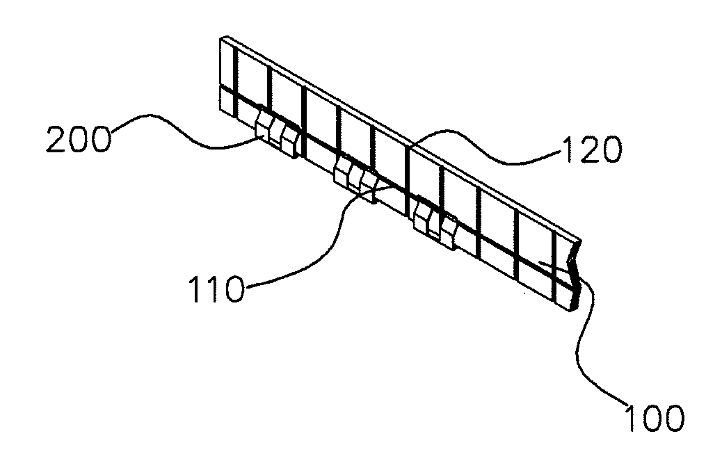
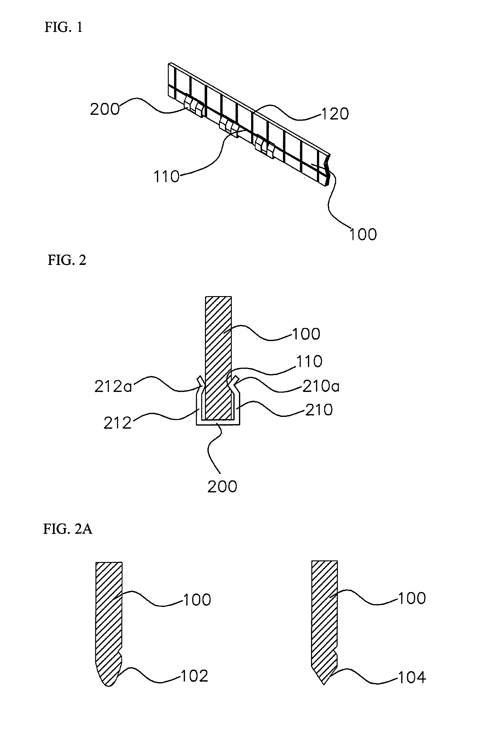
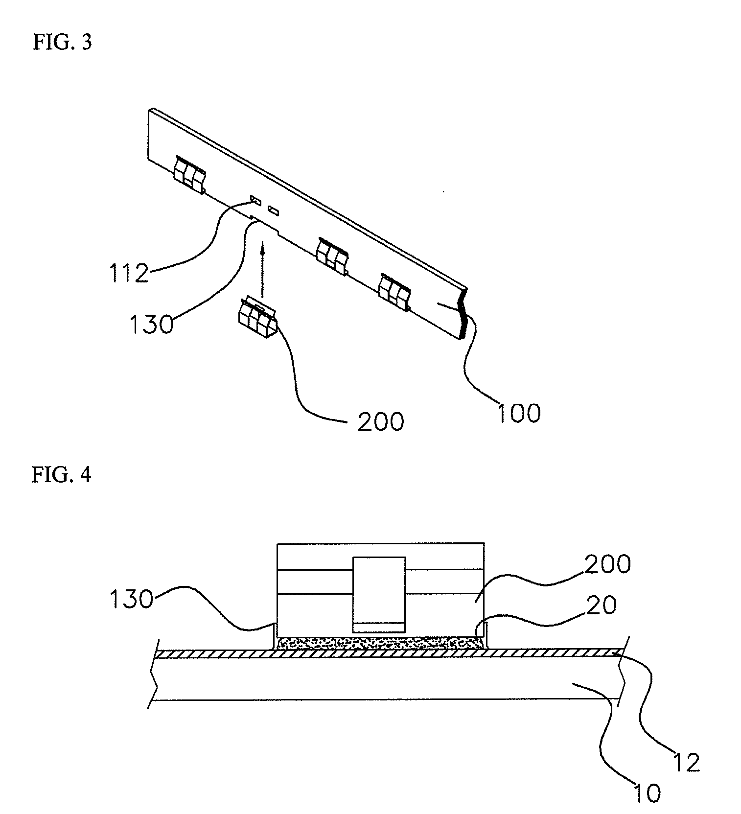
[0031]According to an aspect of the present invention, there is provided a metal strip for an electromagnetic interference shield case, which is uniform in width and thickness, wherein a metal clip that is integrated with at least one pair of elastic parts and is appropriate for soldering is fitted on an end of the metal strip along a width direction of the metal strip, wherein the metal strip is bent and cut so as to have a shape corresponding to a ground pattern disposed on a printed circuit board, and then, a bottom surface of the metal clip is soldered to the ground pattern or a solder member disposed on the ground pattern.

[0032]According to another aspect of the present invention, there is provided an electromagnetic interference shield case including: a metal strip that is uniform in width and thickness, wherein a metal clip that is integrated with at least one pair of elastic parts and is appropriate for soldering is fitted on an end of the metal strip along a width direction...


PUM

PropertyMeasurementUnit
Lengthaaaaaaaaaa
Lengthaaaaaaaaaa
Thicknessaaaaaaaaaa

Abstract

Provided is a metal strip for an electromagnetic interference shield case. The metal strip is uniform in width and thickness. A metal clip that is integrated with at least one pair of face-to-face elastic parts and is appropriate for soldering is fitted on an end of the metal strip along a width direction of the metal strip. The metal strip is bent and cut so as to have a shape corresponding to a ground pattern disposed on a printed circuit board, and then, a bottom surface of the metal clip is soldered to the ground pattern or a solder member disposed on the ground pattern.

Description

FIELD OF THE INVENTION[0001]The present invention relates to a metal strip assembly for an electromagnetic interference (EMI) shield case, and more particularly, to a metal strip assembly that makes it possible for a designer to economically and quickly fabricate an EMI shield case for verifying his / her design, without using an extra tool.[0002]In addition, the present invention relates to an EMI shield case including the metal strip assembly, and a fabrication method of the EMI shield case.BACKGROUND OF THE INVENTION[0003]Along with the trend of high frequency, miniaturization, and high integration, heat, static electricity, and electromagnetic waves significantly affect electronic devices and information / communication devices. For example, as performances of high frequency electronic devices, e.g., the processing speed of microprocessors and the storage capacity of memories are increased, and the size thereof is decreased, they emit a larger amount of heat and electromagnetic wave...

Claims


Application Information

Patent Timeline
IPC IPC(8): H05K9/00H01R43/16H01B5/00
CPCH05K9/0035Y10T29/49218H01R12/51H05K9/00
Inventor KIM, SUN-KI
Owner JOINSET
Learn More