

Non-contact power transmission device and near-field antenna for same
a power transmission device and near-field technology, applied in transmission, transformers, inductances, etc., can solve the problems of limiting the distance between non-contact power transmission and reception, the degree of coupling between the resonance-use inductors of transmitting and receiving antennas is decreased, etc., to achieve the effect of reducing the coupling between the resonance-use inductors of transmitting and receiving antennas, reducing the q-value of the antenna, and improving the efficiency of power transmission
- Summary
- Abstract
- Description
- Claims
- Application Information
AI Technical Summary
Benefits of technology
Problems solved by technology
Method used
Image

Examples
example 1
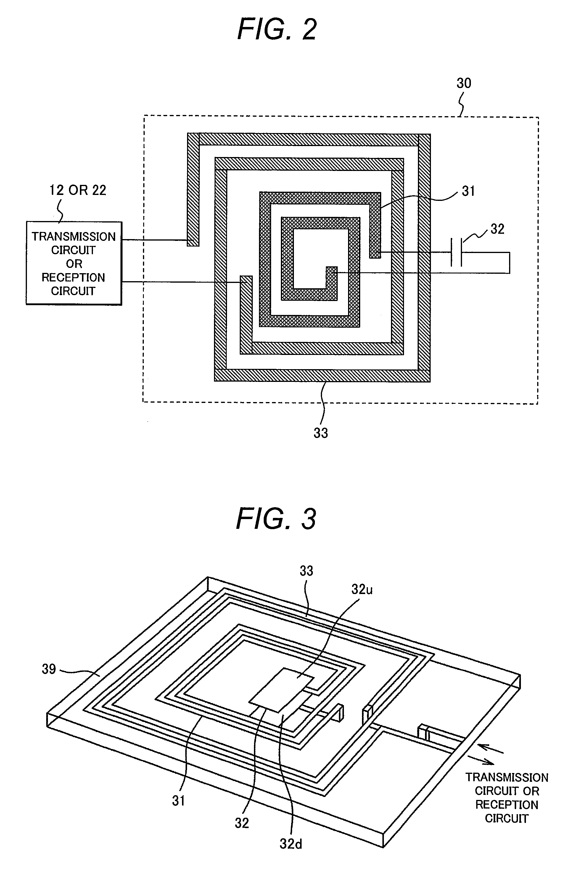
[0047]FIG. 2 accompanying this description shows a theoretical configuration of a near-field antenna for non-contact power transmission as example 1 of the present invention. In FIG. 2, a first inductor 31 for resonance and a second inductor 33 coupled with the first inductor are formed over the same substrate 30. Between both ends of the first inductor 31, a capacitor 32 for frequency adjustment is connected interposingly. And the transmission circuit or reception circuit is connected to both ends of the second inductor. In the configuration of the example 1, the first inductor 31 is positioned inside the second inductor 33 over the same substrate 30. The two inductors exchange energy therebetween through a high degree of electromagnetic induction coupling.
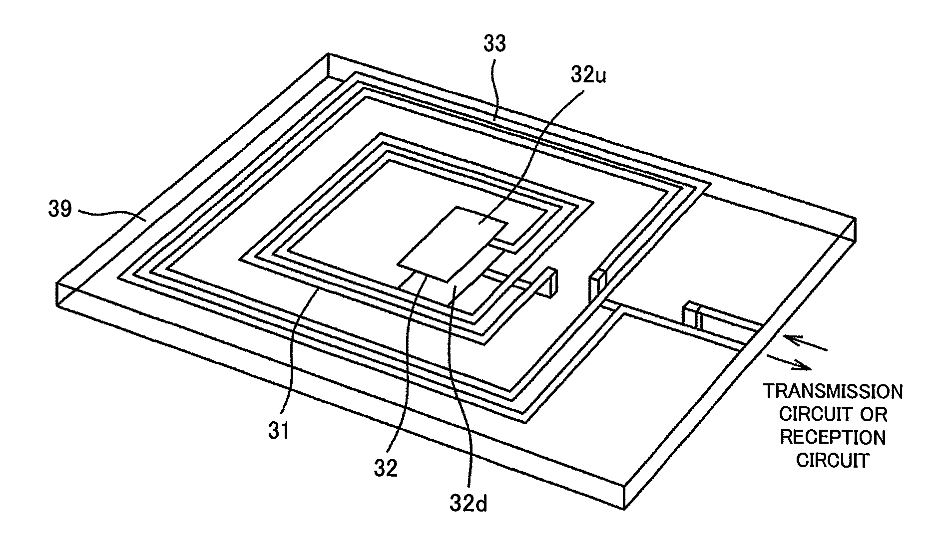
[0048]FIG. 3 accompanying this description is a perspective view of the above-described near-field antenna for non-contact power transmission as the example 1. The first inductor 31 and second inductor 33, both made of thin metal...
example 2
[0054]Next, FIG. 5 shows a theoretical configuration of a near-field antenna for non-contact power transmission as example 2 of the present invention. In the example 2, as in the example 1, the first inductor 31 for resonance and the second inductor 33 coupled with the first inductor are formed over the same substrate 30 made of a dielectric material. However, unlike the example 1, the example 2 has the first inductor 31 positioned outside the second inductor 33 over the same substrate 30. The two inductors exchange energy therebetween through a high degree of electromagnetic induction coupling. Also in the example 2, the capacitor 32 for frequency adjustment is connected to the first inductor 31, and the above-mentioned transmission circuit or reception circuit is connected to the second inductor 33.
[0055]FIG. 6 is a perspective view of the near-field antenna for non-contact power transmission as the above-described example 2. The first inductor and the second inductor, both made o...
example 3
[0057]Next, FIG. 7 accompanying this description shows a theoretical configuration of a near-field antenna for non-contact power transmission as example 3 of the present invention. That is, in the example 3, the first inductor 31 for resonance is formed over the same dielectric substrate 30, with both ends of the inductor 31 connected to the capacitor 32 for frequency adjustment. Unlike the above-described example 1 or 2, the example 3 has a second capacitor 34 positioned adjacent to the (first) capacitor 32 for frequency adjustment without the second inductor being formed over the same substrate 30. The second capacitor 34 is connected to the transmission circuit or reception circuit.
[0058]FIG. 8 accompanying this description is a perspective view of the above-described near-field antenna for non-contact power transmission. As can be seen from this perspective view, the first capacitor 32 and the second capacitor 34 are positioned in close proximity to each other along with the fir...
PUM
 Abstract
Description
Claims
Application Information