Region based vision tracking system for imaging of the eye for use in optical coherence tomography

a vision tracking and eye imaging technology, applied in the field of optical coherence technology, can solve the problems of data not being able to line up properly, scanning takes a certain amount of time, and the eye cannot move in time, so as to eliminate the effect of the eye movement and accurate offs

a vision tracking and eye imaging technology, applied in the field of optical coherence technology, can solve the problems of data not being able to line up properly, scanning takes a certain amount of time, and the eye cannot move in time, so as to eliminate the effect of the eye movement and accurate offs

US20130010259A1Inactive Publication Date: 2013-01-10SONOMED IP HLDG

Image

  • Region based vision tracking system for imaging of the eye for use in optical coherence tomography
  • Region based vision tracking system for imaging of the eye for use in optical coherence tomography
  • Region based vision tracking system for imaging of the eye for use in optical coherence tomography

Examples


Embodiment Construction

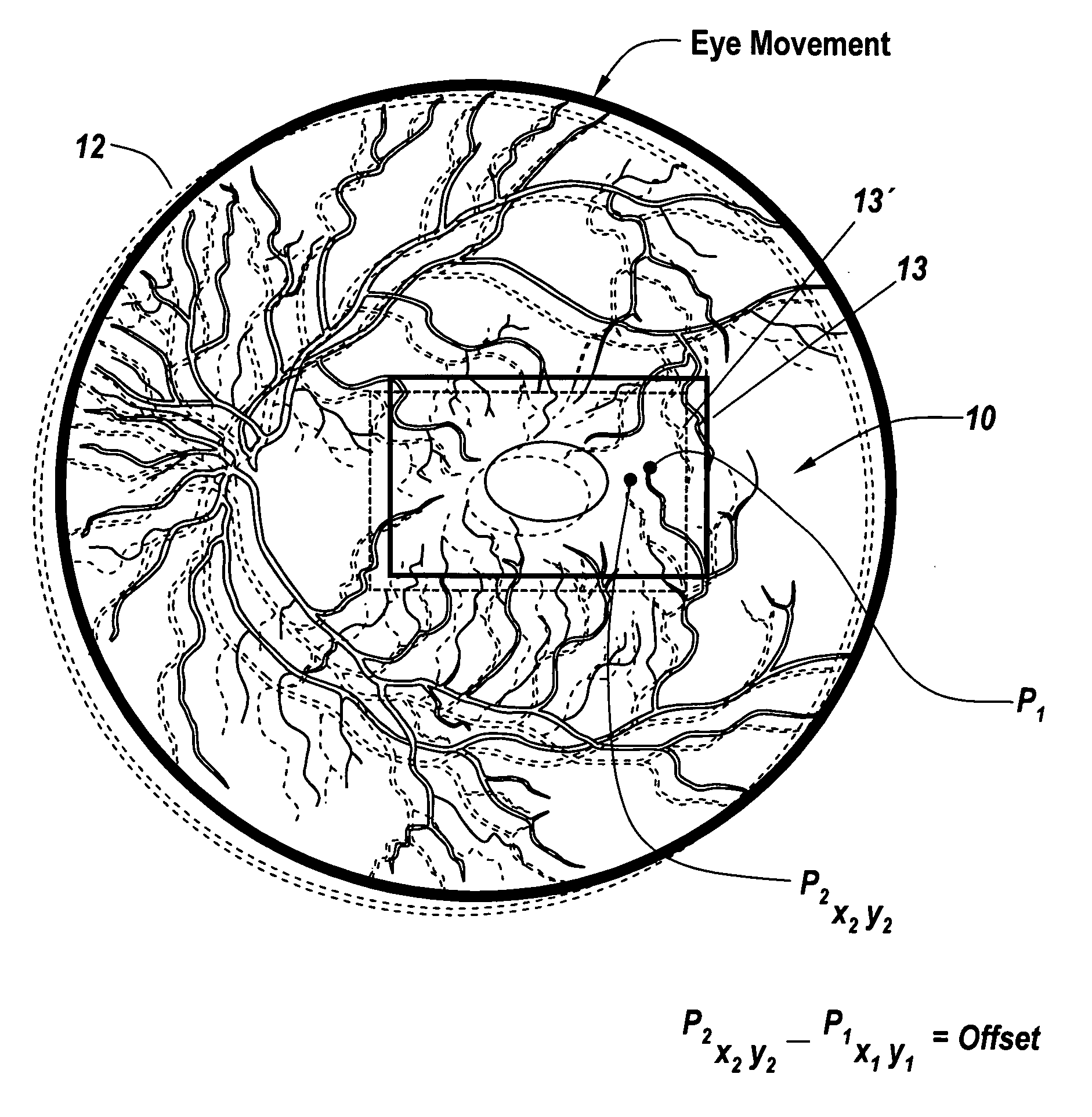
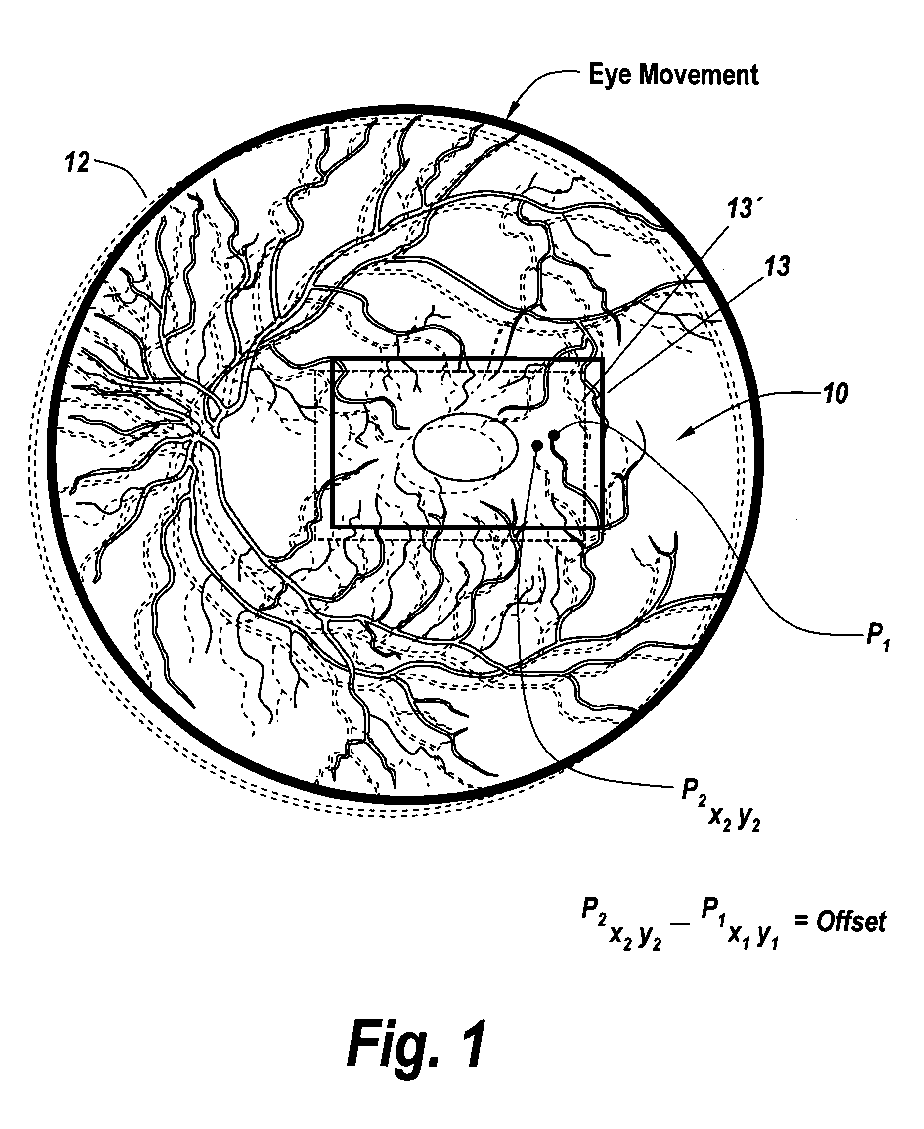
[0037]Referring now to FIG. 1, an image 10 of the retina of an eye is illustrated having a data rich region of features including vessels and other artifacts clearly visible on the surface of the retina. Eye movement is shown in dotted line in which the eye moves as illustrated by dotted line 12 resulting in movement of the data rich region image of the retina as viewed by an auxiliary imager.

[0038]Here it can be seen a point in a data rich region 13 which constitutes for instance a reference tracking feature moves from point P1 at X1 Y1 to P2 at X2 Y2. This corresponds to a shift in region 13 as shown by dotted outline 13′. Note that region 13 of the retina sensed includes virtually hundreds and even thousands of these points, the movement of which is calculated through comparing a registration process so as to take advantage of all of the information that is available in the region. This is contrasted to the use of a single line which carries with it a number of artifacts that cor...


PUM


Abstract

For optical coherence tomography engines a method for eliminating the effects of the movement of the eye on the optical coherence tomography scan calculates the motion of the eye from an image from an auxiliary scanning system and compares a reference region to a corresponding region in the image associated with the next frame, with the change in position sensing the motion of the eye. This is followed by utilizing this sensed motion to generate accurate offsets for the scanning mirror patterns of the OCT engine. Additionally, scan skipping is utilized to obviate the effects of rapid eye movement that occur at rates faster than the image acquisition rate.

Description

FIELD OF THE INVENTION[0001]This invention relates to optical coherence technology and more particularly to region-based image tracking for eliminating the effects of the movement of the eye on the optical coherence tomography scan.BACKGROUND OF THE INVENTION[0002]Optical coherence tomography (OCT) is a technology for performing high resolution cross sectional imaging that can provide images of tissue structure on the micron scale in vivo and in realtime. OCT is a method of interferometry that uses light containing a range of optical frequencies to determine the scattering profile of a sample. Optical coherence tomography as a tool for evaluating biological materials was first disclosed in the early 1990s and is described in U.S. Pat. No. 5,321,501 in which the optical coherence tomography was used for fundus imaging. While there are various systems for obtaining time domain cross sectional images of the retina, in recent years it has been demonstrated that frequency domain OCT has ...

Claims


Application Information

Patent Timeline
10 Jan 2013
Publication
US20130010259A1
IPC
A61B3/113; A61B3/14
CPC
A61B3/102
Inventors
CARNEVALE, MATTHEW