Wireless transmission system and wireless transmitter, wireless receiver, wireless transmission method wireless reception method and wireless communication method used with same

a wireless transmission and wireless receiver technology, applied in selective content distribution, amplitude demodulation, instruments, etc., can solve problems such as hdtv appearance compromising, and achieve the effects of reducing the level of disturbing waves, low price, and low power consumption without compromising transmission quality

Inactive Publication Date: 2013-01-10
SILICON LIBRARY
View PDF0 Cites 37 Cited by
  • Summary
  • Abstract
  • Description
  • Claims
  • Application Information

AI Technical Summary

Benefits of technology

[0052]According to the present invention, millimeter-wave carrier signals from carrier oscillators provided for their respective channels of a transmission path are subjected to on-off keying modulation on a channel-by-channel basis and then transmitted wirelessly. The radio signals subjected to on-off keying modulation are down-converted using millimeter-wave local signals from local oscillators provided for their respective channels and therefore demodulated into the original digital signals. In this manner, in the present invention, radio signals are modulated by on-off keying and demodulated simply on the basis of envelope information for the radio signals subjected to on-off keying modulation, and therefore unlike in the conventional art, high-quality demodulation can be achieved without carrier frequencies being accurately fixed on the transmission side and also without local frequencies being accurately fixed on the reception side. Accordingly, for on-off keying modulation and demodulation based on envelope information, carrier and local frequencies are not required to be fixed accurately, and therefore the need for PLL circuits is eliminated. Moreover, in the case of OOK modulation, it is possible to eliminate the need for high-speed processing circuits for parallel-serial conversion and look-up tables for serial-parallel conversion. Thus, the wireless transmitter and the wireless receiver make it possible to eliminate the need for PLL circuits, high-speed processing circuits, and look-up tables. Accordingly, it is possible to provide a wireless transmission system for wirelessly transmitting a digital signal from one device to another at low price and low power consumption without compromising transmission quality, along with a wireless transmitter, a wireless receiver, a wireless transmission method, a wireless reception method, and a wireless communication method for use with the same system.
[0053]Furthermore, by setting radio signals to have different planes of polarization from their adjacent channels, it is rendered possible to reduce the level of a disturbing wave in a radio signal to be received, so that high-qualit

Problems solved by technology

In the case of the wall-hanging HDTV, an HDMI cable being laid on the wal

Method used


Image

  • Wireless transmission system and wireless transmitter, wireless receiver, wireless transmission method wireless reception method and wireless communication method used with same
  • Wireless transmission system and wireless transmitter, wireless receiver, wireless transmission method wireless reception method and wireless communication method used with same
  • Wireless transmission system and wireless transmitter, wireless receiver, wireless transmission method wireless reception method and wireless communication method used with same

Examples


first embodiment

Examples of the First Embodiment

[0142]The present inventors manufactured prototypes of the first embodiment and confirmed a bit error ratio (BER) and power consumption by principal parts. FIG. 10 is a block diagram illustrating functional features of a prototype of the wireless HDMI transmitter 100. In FIG. 10, the wireless HDMI transmitter 100 includes an HDMI connector 112, a DAC (digital to analog converter) 113, a connector 114, a DC +5V power connector 115, and resistors 116, 117, and 118, which are all formed on an FR4 (flame retardant type 4) board, and also includes a millimeter-wave transmitter 101. The millimeter-wave transmitter 101 can be attached to / removed from the connector 114. Note that because the wireless HDMI transmitter 100 is a prototype, DC +5V is independently supplied for experimental simplicity, but in an actual product, DC +5V may be supplied via the HDMI connector 112. Note that in a wireless HDMI receiver 200 shown in FIG. 11, an HDMI connector 216 does ...

second embodiment

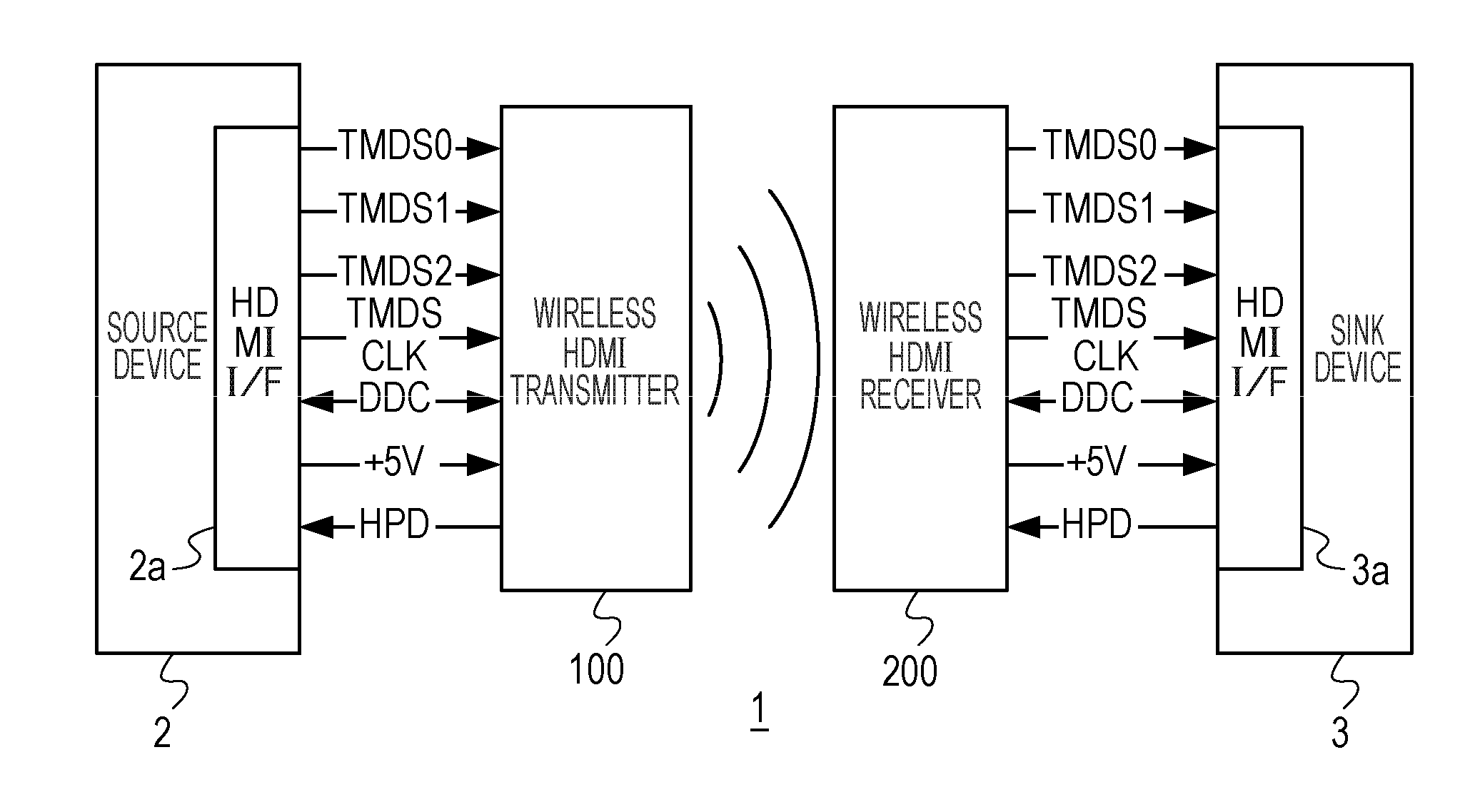
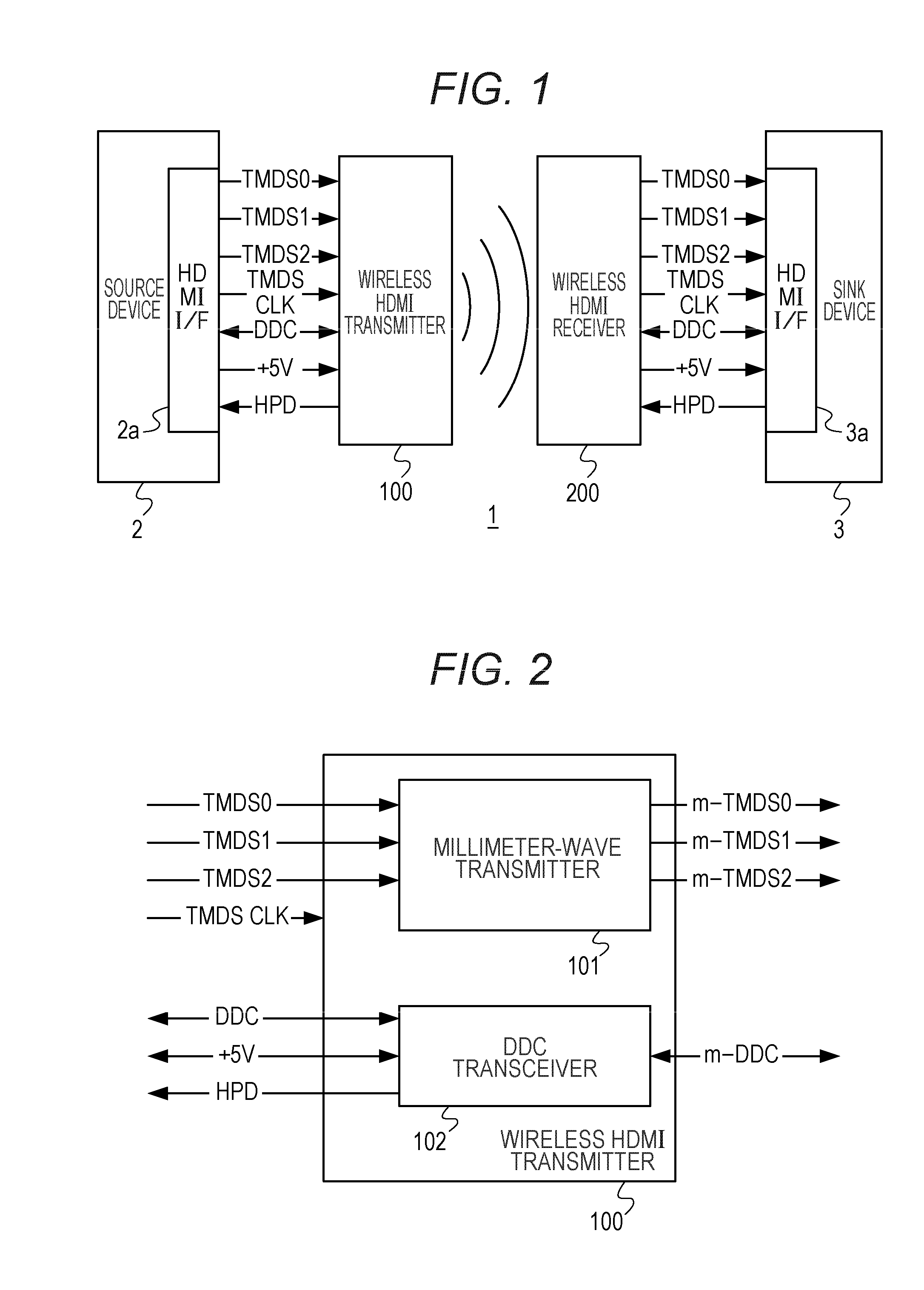
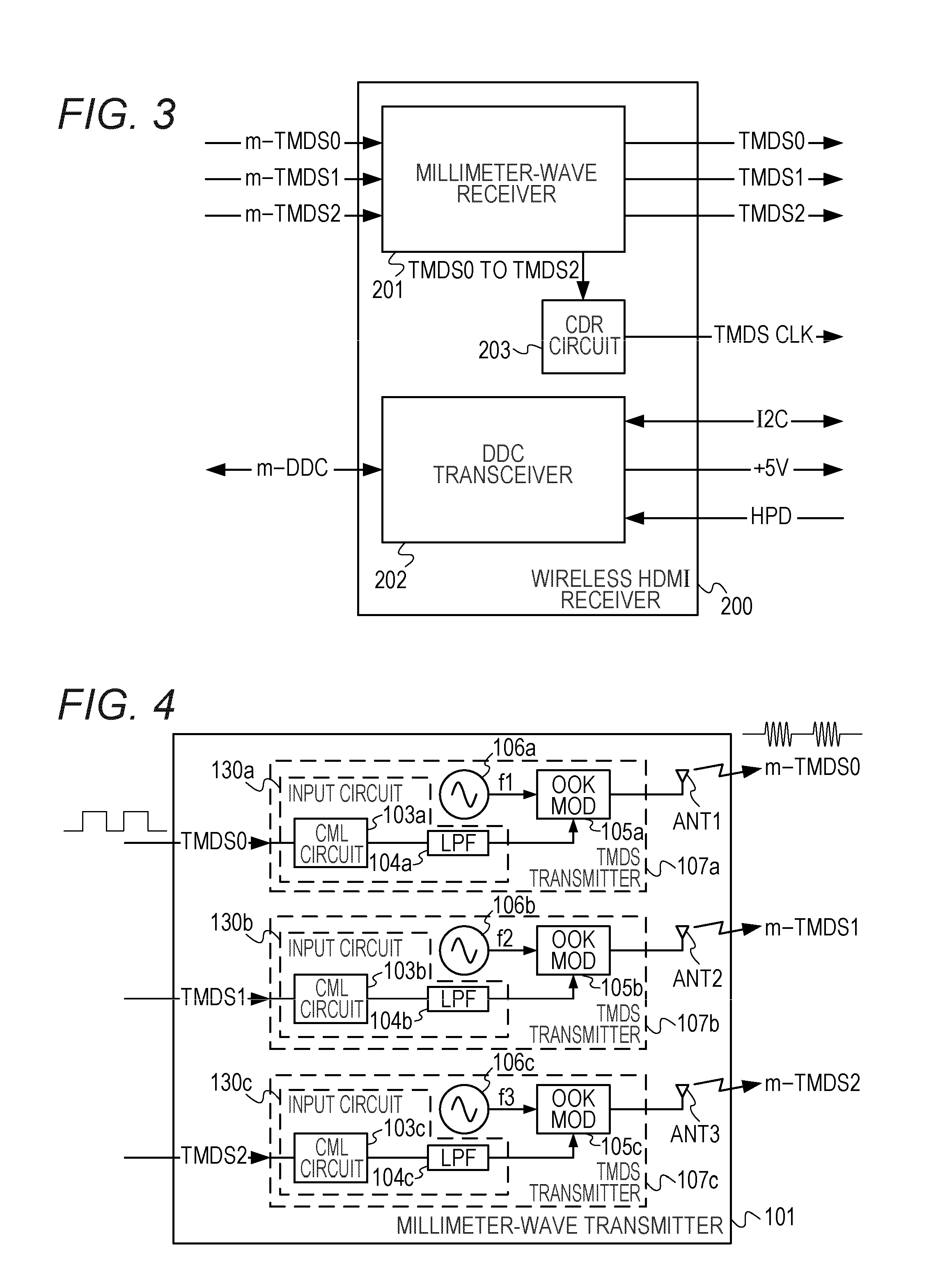
[0186]FIG. 1 is referenced for the overall configuration of a wireless transmission system 1 in a second embodiment because it is generally the same as in the first embodiment. Moreover, FIGS. 2 and 3 are referenced for the schematic configurations of the wireless HDMI transmitter 100 and the wireless HDMI receiver 200 because they are generally the same as in the first embodiment. The second embodiment differs from the first embodiment regarding the configuration of a millimeter-wave transmitter 401. Specifically, the millimeter-wave transmitter 401 of the second embodiment differs from the millimeter-wave transmitter 101 of the first embodiment in that PLL circuits are provided for locking VCOs 106a to 106c of TMDS transmitters 107a to 107c only at predetermined times. Moreover, a millimeter-wave receiver 501 of the second embodiment differs from the millimeter-wave receiver 201 of the first embodiment in that PLL circuits are provided for locking TMDS receivers 207a to 207c only ...

third embodiment

[0194]In a third embodiment, as frequency adjustment portions, frequency counters are used in place of the PLL circuits used in the second embodiment. Hereinafter, differences from the second embodiment will be described. FIG. 20 is a block diagram illustrating functional features of a millimeter-wave transmitter 409 in the third embodiment of the present invention. In FIG. 20, elements that function generally in the same manner as in the millimeter-wave transmitter 101 in the first embodiment are denoted by the same reference characters, and any descriptions thereof will be omitted. The millimeter-wave transmitter 409 is provided with frequency adjustment portions 410a to 410c for adjusting the oscillation frequencies of the VCOs 106a to 106c. Each of the frequency adjustment portions 410a to 410c includes a frequency divider 411, a frequency counter 412, registers 413 and 414, a frequency comparator 415, and a digital-analog converter 416.

[0195]The frequency divider 411 divides an...


PUM


Abstract

A wireless transmission system includes a wireless HDMI transmitter and a wireless HDMI receiver. The wireless HDMI transmitter includes a carrier oscillator provided for each channel of an HDMI transmission path to output a carrier signal in a millimeter band, an OOK modulator provided for each carrier oscillator to perform on-off keying modulation on a carrier signal outputted by its corresponding carrier oscillator, and an input circuit provided for each channel of the HDMI transmission path to input a digital signal outputted by a source device to the OOK modulator. Radio signals have different planes of polarization from their adjacent channels.

Description

TECHNICAL FIELD[0001]The present invention relates to wireless transmission systems and also to wireless transmitters, wireless receivers, wireless transmission methods, wireless reception methods and wireless communication methods for use with the same, and more particularly, the invention relates to a wireless transmission system using millimeter waves and also to a wireless transmitter, a wireless receiver, a wireless transmission method, a wireless reception method and a wireless communication method for use with the same.BACKGROUND ART[0002]Most of the high-definition plasma televisions, liquid crystal televisions, digital projectors, DVD players and Blu-ray players that are available in the market today include high-definition multimedia interface (HDMI) connectors. By using an HDMI connector, a source device (e.g., a digital set-top box, a DVD player, a Blu-ray player, an HDD player or the like) can very reliably transfer digital content to a sink device (e.g., a high-definit...

Claims


Application Information

Patent Timeline
IPC IPC(8): H04L27/04H04L27/06
CPCH04L5/06H04L27/04H04N21/43637G09G2370/22G09G2370/045G09G2370/12G09G2370/16G09G5/006
Inventor SHIMIZU, JUNZOHFUJISHIMA, MINORUOHTA, MASAHIKOTAKADA, TOSHIO
Owner SILICON LIBRARY
Why Eureka
Try Eureka