System and Method for Pedicle Screw Placement in Vertebral Alignment

a technology of vertebral alignment and pedicle screw, which is applied in the field of system and method of pedicle screw placement in vertebral alignment, can solve the problems of patient discomfort, long recovery time, and traumatic time, and achieve the effects of reducing cost, improving surgical control, and speeding up the complexity of spine surgery procedures

Inactive Publication Date: 2013-01-10
SPINAL USA
View PDF5 Cites 43 Cited by
  • Summary
  • Abstract
  • Description
  • Claims
  • Application Information

AI Technical Summary

Benefits of technology

[0011]The system and method of the invention illustrate a variety of structures and techniques to enable a staged location and entry into the pedicle for providing insertive, progressively larger threaded fixation and superior surgical control from a distance from the spine. The subject pedicle screw placement system can be used with any current imaging technology, which may include x-ray...

Problems solved by technology

In the past, surgical procedures, spinal surgical procedures in particular, were quite invasive, traumatic, and time consuming.
As a result, such surgeries lead to long recovery time, patient discomfort, an increased risk of infection, and high expense.
However, the smaller exposure of the surgical field has presented a challenge to the surgeon to accomplish the same goals of a successful open procedure with a technique having less direct visualization of the operative site.
Unfortunately, trocar needles are often flimsy and prone to bending or breaking.
In such circumstances, the clinician must expend additional time and effort to extract and replace the trocar, thereby increasing the likelihood of complications.
Further, due to its flimsiness, the trocar needle can be difficult to properly dock in hard pedicle bone.
As unders...

Method used


Image

  • System and Method for Pedicle Screw Placement in Vertebral Alignment
  • System and Method for Pedicle Screw Placement in Vertebral Alignment
  • System and Method for Pedicle Screw Placement in Vertebral Alignment

Examples


Embodiment Construction

[0034]The subject invention provides improved systems and methods for pedicle screw placement. According to the subject invention, the systems and methods described herein enable minimally invasive surgical procedures in pedicle screw placement without the need for a trocar needle and / or guidewires.

[0035]The systems described herein are made of biocompatible material for surgical implantation such as stainless steel, titanium and titanium-based alloys, combination metallic alloys and the like; various plastics, ceramics, biologically absorbable materials, and the like. Other biocompatible materials that can be used to produce the systems of the invention are well-known to the skilled artisan.

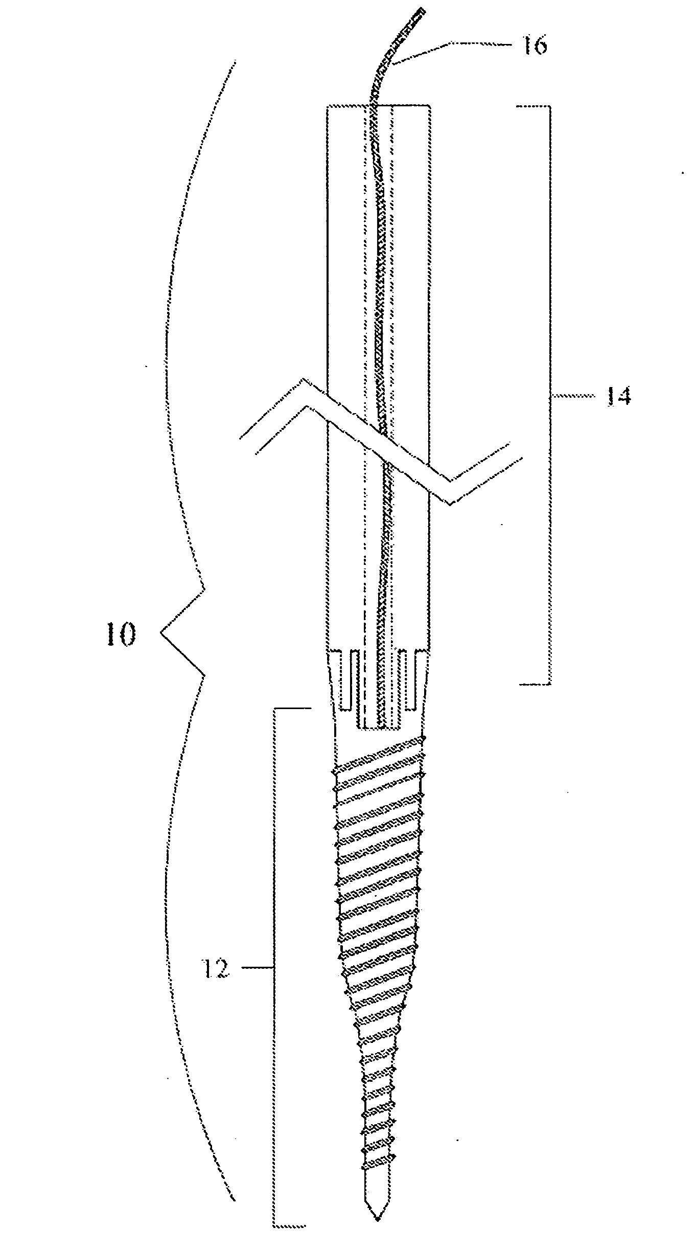
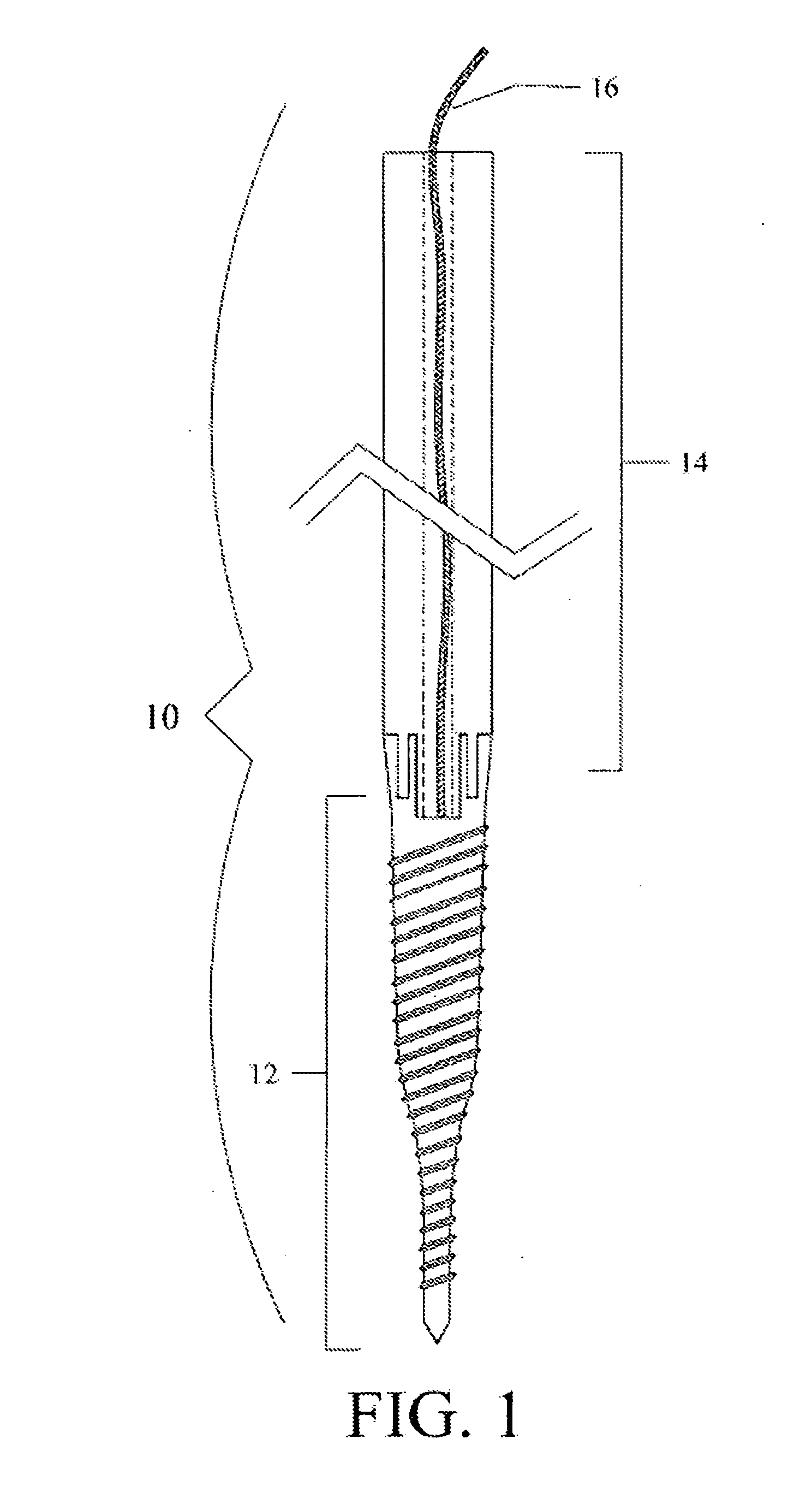
[0036]Referring to FIG. 1, a pedicle finder 10 is illustrated. The pedicle finder 10 comprises a pedicle anchor 12, an extender 14, and a flexible tether 16 that is attached to the pedicle anchor 12. Essentially, the pedicle finder 10 is a device that can have its tip member (pedicle anchor 12) ...


PUM


Abstract

A system and minimally invasive method for the placement of pedicle screws without the use of a trocar needle and/or guidewires. The system and method comprises at least one pedicle finder and at least one dilator. The pedicle finder preferably comprises an extender that is removably attached to a pedicle anchor. Attached to a pedicle anchor is a flexible tether. The extender preferably includes a passage through which the flexible tether extends. The dilator comprises a tubular body with two ends, where a first end comprises a means for securing the dilator into bony process of vertebra and a second end comprises at least two arm attachments. The tubular body Of the dilator is configured to slide easily over an extender and secure the first end into bony vertebra to prevent the dilator from dislodging. The arm attachment of the second end of the dilator can be interconnected with another arm attachment via a linking element and/or the dilator can be secured to a stable object such as a table via a securing element.

Description

CROSS-REFERENCE TO A RELATED APPLICATION[0001]This application claims the benefit of U.S. provisional application Ser. No. 61 / 314,619, filed Mar. 17, 2010, which is incorporated herein by reference in its entirety.BACKGROUND OF THE INVENTION[0002]In the past, surgical procedures, spinal surgical procedures in particular, were quite invasive, traumatic, and time consuming. Such surgeries typically utilized large incisions and extensive tissue retraction, where muscle and ligament tissues were retracted or surgically detached during surgery and reattached afterward. As a result, such surgeries lead to long recovery time, patient discomfort, an increased risk of infection, and high expense.[0003]In an attempt to address these issues, minimally invasive surgical procedures have been devised. The advantages for the patient, when implementing such procedures, have been well documented with less pain, blood loss and tissue damage all contributing to a faster recovery and improved function ...

Claims


Application Information

Patent Timeline
IPC IPC(8): A61B17/56
CPCA61B17/1671A61B17/7001A61M29/00A61B17/8635A61B17/8897A61B17/708
Inventor LIN, DEAN
Owner SPINAL USA
Why Eureka
Try Eureka