
Pipettes, methods of use, and methods of stimulating an object of interest

a pipette and object technology, applied in the field of pipette, methods of use, and methods of stimulating objects of interest, can solve the problems of contaminating other cells or surfaces, difficult to use conventional glass pipette in order, and unfavorable penetration, and achieve the effect of enhancing vibration stability

Active Publication Date: 2013-01-17
FLUICELL AB
View PDF5 Cites 10 Cited by
  • Summary
  • Abstract
  • Description
  • Claims
  • Application Information

AI Technical Summary

Benefits of technology

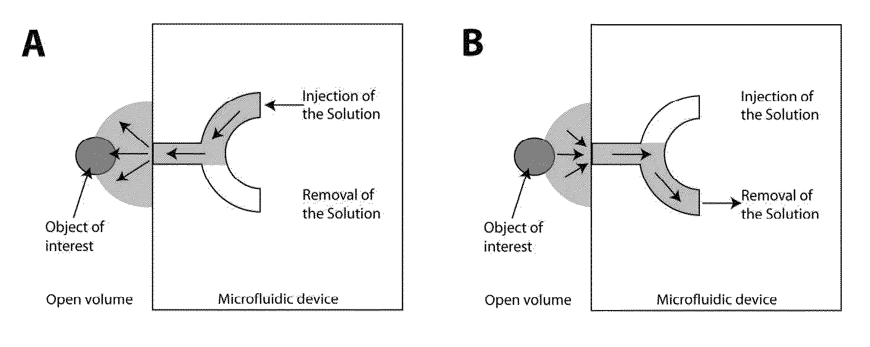
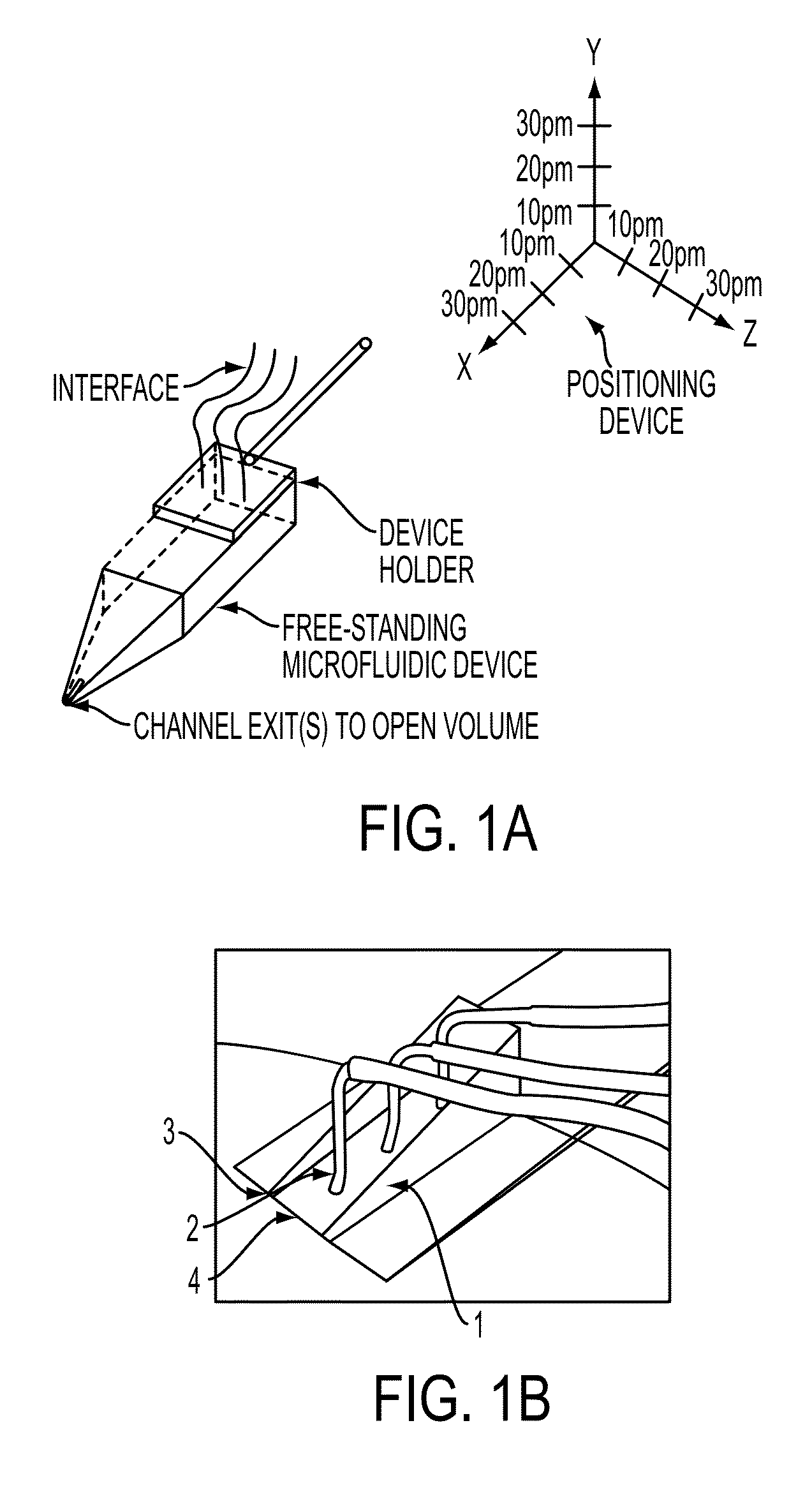
The invention provides a small pipette that can deliver fluids with high precision and without contamination. It has both a solution exchange and fluid re-circulation capability, allowing for controlled delivery in close proximity to the pipette outlet. The device can be positioned accurately using micro- or nanopositioning techniques, making it suitable for applications such as biological or artificial cell analysis, surface area definition, or sensor element detection. The device may also be mechanically bent to improve stability during vibration.

Problems solved by technology

However, penetration may often be unfavorable, since it can destroy or deteriorate the internal structure of the cell and affect its normal physiology.
However, conventional glass pipettes are difficult to use in order to establish a non-mechanical, purely chemical contact with a microscopic object.
The constant injection on the other hand will cause accumulation of active substrate outside of the microscopic experimental region, which contaminates other cells or surfaces and severely limits further studies in the same system.
However, these devices may result in cross-contamination and do not allow spatial concentration control with high precision.
However, conventional microfluidic devices lack an important capability of a pipette, which is the control of position relative to the macroscopic reservoir, or open volume.
This considerably restricts the applicability of the superfusion device and makes it considerably more difficult to expose an arbitrary region such as a cell, microfabricated structures, sensors, and / or actuators attached on a surface, a single cell in a large cell culture or tissue, extended structures built on a surface (e.g., lipid-nanotube networks), and micro / nanofabricated objects on a surface.
Stable microscopic chemical gradients are difficult to achieve with macroscopic tools.
In addition, various mechanical and practical problems may be associated with glass pipettes, such as backfilling, breaking upon accidental contact with surfaces or objects, damage to cells and tissue, adsorption of chemical agents or biological matter to the glass surface, the need for specialized pulling equipment, and the need for a specifically designed needle holder.

Method used


Image

  • Pipettes, methods of use, and methods of stimulating an object of interest
  • Pipettes, methods of use, and methods of stimulating an object of interest
  • Pipettes, methods of use, and methods of stimulating an object of interest

Examples


example device

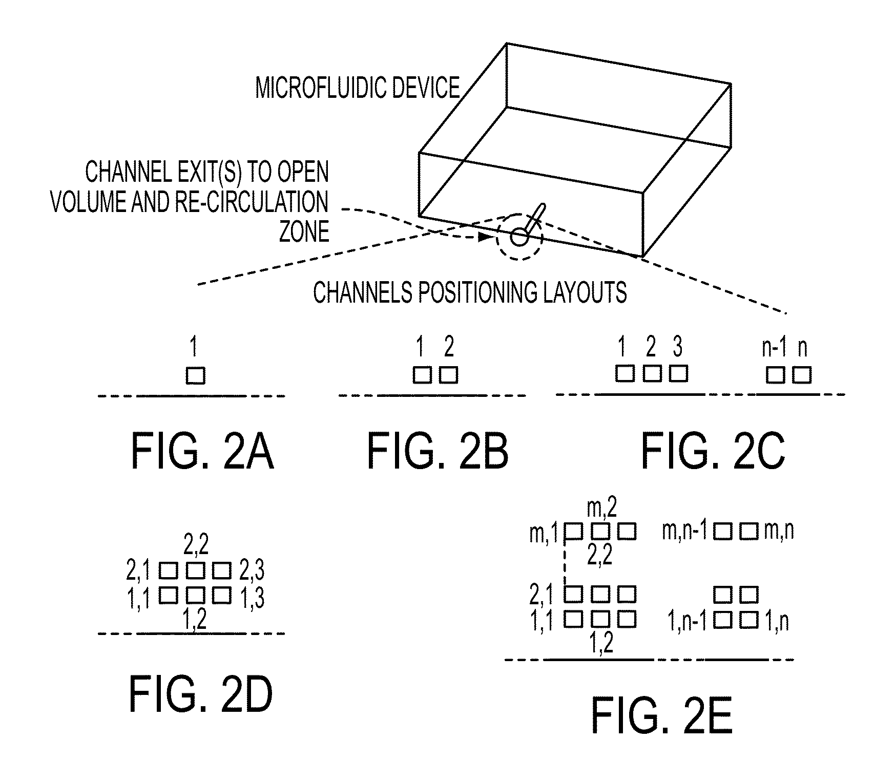
[0220]An example of a device capable of changing the composition of the re-circulation zone over time by multiplexing between several liquid inputs is shown in FIG. 22A. Channel exits are located at the tapered tip of the microfluidic device to facilitate applicability. The device interface contains three solution inputs (marked as solution 1, 2 and 3), two switching controls (marked as switch 1 and 2) two waste outputs (marked as waste 1 and 2) and one re-circulation output. (FIG. 22A) The flow is pressure driven. All solution inputs are pressured at pressure +P, while switching controls can be pressurized to the same pressure (+P) or to the atmospheric pressure (0).

[0221]Pressure +P can, in some embodiments, range from about 2 kPa to about 100 kPa. For example, pressure +P can be selected from the group consisting of: between about 2 kPa and about 10 kPa, between about 10 kPa and about 20 kPa, between about 20 kPa and about 30 kPa, between about 30 kPa and about 40 kPa, between ab...


PUM

PropertyMeasurementUnit
widthaaaaaaaaaa
distanceaaaaaaaaaa
distanceaaaaaaaaaa

Abstract

The present invention features a freestanding microfluidic pipette with both solution exchange capability and fluid re-circulation, enabling highly localized and contamination- free fluid delivery within a confined volume in the vicinity of the pipette exit. Preferably, the device features direct positioning, so the pipette can be directed at a point or object of interest, such as a biological or artificial cell, a defined surface area or a sensor element within an open volume, using micro- or nanopositioning techniques. One aspect of the invention provides a free-standing pipette. The free-standing pipette includes a microfluidic device comprising one or more channels with exits leading into an open-volume and a positioning device programmed to hold the microfluidic device at an angle from a horizontal axis.

Description

CROSS-REFERENCE TO RELATED APPLICATION[0001]This application claims the benefit of International Application No. PCT / IB2010 / 003307, filed Dec. 3, 2010, which claims priority to U.S. Provisional Patent Application No. 61 / 266,255, filed Dec. 3, 2009. The entire contents of each of these applications is hereby incorporated herein by reference.BACKGROUND OF THE INVENTION[0002]Since their invention, glass micropipettes have been indispensable tools for molecular and cellular biologists. They can be used for microinjection to mechanically penetrate the cell's membrane and inject or sample material to and from the cell's interior. Examples include transplanting the nucleus, making molecular cloning possible. Micropipettes can also be used to make electrical contact to the cell interior, which is the foundation of the patch-clamp technique.[0003]Glass micropipettes are suited for establishing a mechanical contact with a single cell by penetrating through the lipid membrane. However, penetra...

Claims


Application Information

Patent Timeline
Patent Type & Authority Applications(United States)
IPC IPC(8): G01N33/00G01N1/00G01N27/26G01N33/53C12M1/34B01D61/42B01L3/00G01N33/566
CPCB01L3/022B01L3/5027B01L3/502715B01L3/50273Y10T436/25B01L2300/0877B01L2400/0487G01N33/48728B01L2200/0694G01N27/44743G01N27/44791B01L2200/06B01L2300/0645B01L2400/0415
Inventor ORWAR, OWEAINLA, ALARJESORKA, ALDO
Owner FLUICELL AB
Learn More