

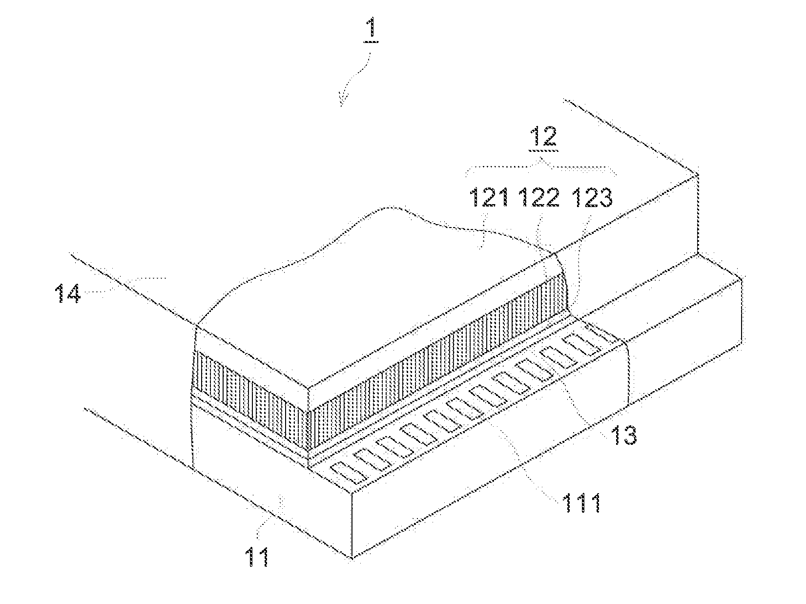
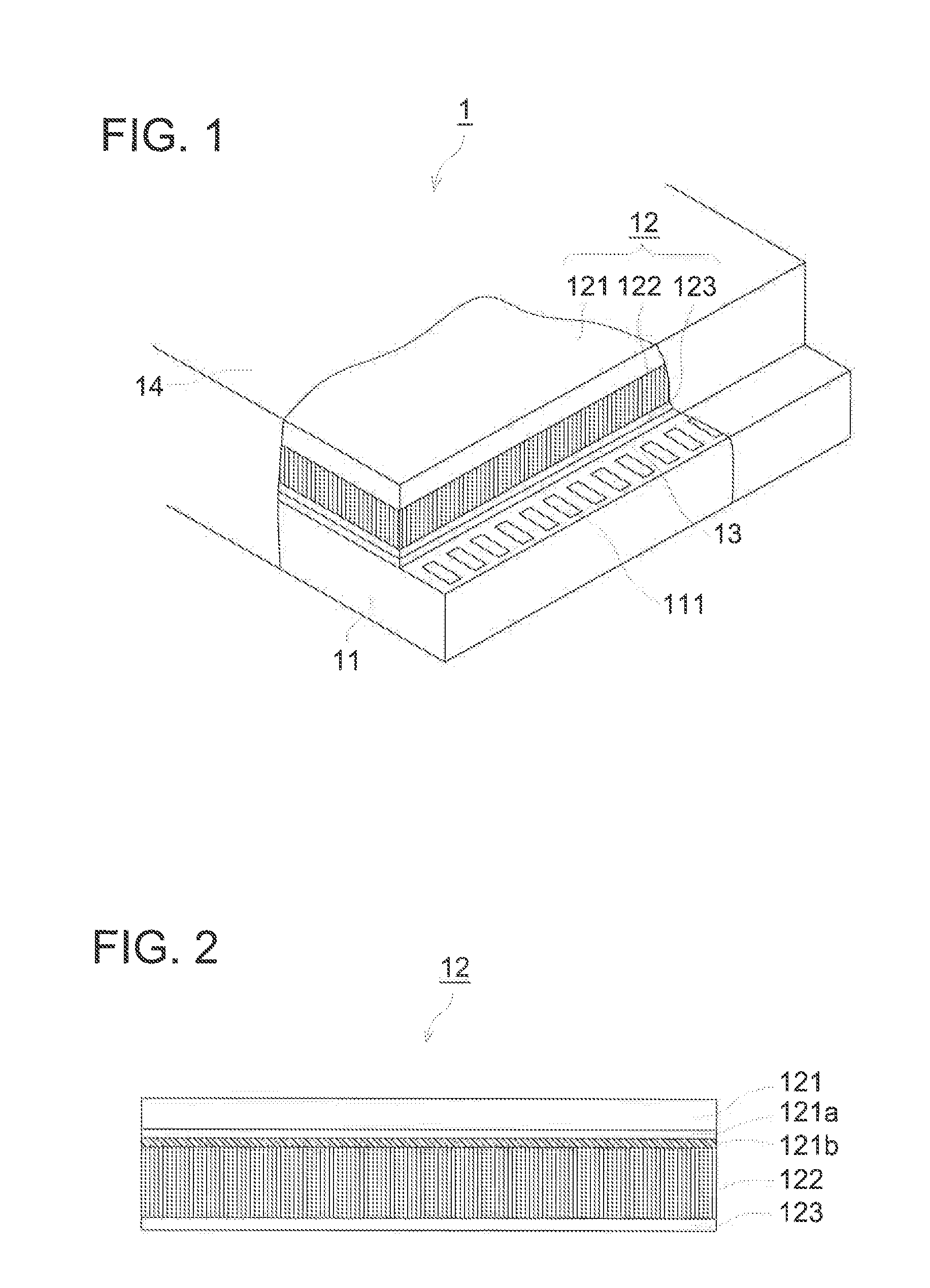
Method of manufacturing flat panel detector
a detector and flat panel technology, applied in the direction of instruments, x/gamma/cosmic radiation measurement, transportation and packaging, etc., can solve the problems of inability to use an image formation region, difficult to cut out the fee phosphor layer after evaporation, and inability to use free image processing or instant electrical transmission, etc., to achieve the effect of small area, not a non-imaging region, and excel in productivity
- Summary
- Abstract
- Description
- Claims
- Application Information
AI Technical Summary
Benefits of technology
Problems solved by technology
Method used
Image

Examples
example
[0189]Although the present invention will be explained in detail hereafter with reference to examples, the present invention is not limited to these examples.
(Production of Substrate)
[0190]A reflecting layer (0.1 μm) was formed on each of the following Substrates with a size of 600×600 mm by spattering silver.
SubstrateMaterialThicknessA-1Aluminium0.2mmA-2Aluminium0.3mmA-3Aluminium0.5mmA-4Aluminium1.0mmA-5Aluminium1.5mmC-1Amorphus carbon0.5mmC-2Amorphus carbon1.0mmG-1Glass1.0mmP-1Polyimide film0.03mmP-2Polyimide film0.05mmP-3Polyimide film0.125mmP-4Polyimide film0.225mmP-5Polyethylenenaphthalate0.125mm
(Production of Comparative Substrate (BL-1, -2))
[0191]As comparative example, a substrate made of amorphous carbon with a thickness of 1.0 mm cut out beforehand in a size of 24.7 mm×49,3 mm was prepared, and the substrate was not subjected to a cutting process and designated to Comparative substrate BL-1.
[0192]A substrate made of polyimide film with a thickness of 0.125 mm cut out befor...
PUM
| Property | Measurement | Unit |
|---|---|---|
| thickness | aaaaa | aaaaa |
| thickness | aaaaa | aaaaa |
| thickness | aaaaa | aaaaa |
Abstract
Description
Claims
Application Information