
Head recognition method

a recognition method and head technology, applied in the field of head recognition method, can solve the problems of many drawbacks of physical input devices, limited amount of different input signals, and inability to recognize heads, etc., and achieve the effect of reducing false positives and increasing the reliability of the method according to the invention

Active Publication Date: 2013-01-24
SOFTKINETIC SOFTWARE
View PDF9 Cites 12 Cited by
  • Summary
  • Abstract
  • Description
  • Claims
  • Application Information

AI Technical Summary

Benefits of technology

The present invention relates to a method for recognizing human heads in images. The method uses an elliptical Hough transform to detect the contour of the human body, and particularly the head, in an image. The ratio of actual human head size to body height remains relatively constant, so the main variable that affects the apparent size of the head in an image is the distance to the head. The method also uses a morphological dilation to increase the chances of recognizing the head. Additionally, the method includes steps to discriminate false positives caused by contours of arms and legs, and to increase the reliability of the method by combining at least two different, but rapid methods of head recognition. The technical effects of the invention are improved speed and accuracy in recognizing human heads in images.

Problems solved by technology

Interaction with computer systems, and, in particular the input of data and commands, is a generally known issue.
However, such physical input devices have many drawbacks.
For instance, they can only offer a limited amount of different input signals, which in some applications such as three-dimensional “virtual reality” environments will feel awkward and lack realism.
Moreover, they are susceptible to wear and their continued use may even have negative consequences for the user's health, such as Repetitive Strain Injury (RSI).
However, voice recognition is not a practical alternative for some applications, such as action games, where rapid, precise and repetitive inputs by the user are required.
Moreover, their effectiveness is adversely affected by background noise, and they generally require a learning period to recognise a particular user's voice commands.
However, conventional imaging systems have no perception of depth and can produce merely a 2D projection of said user.
As a result, the recognition of the user's gestures is inherently flawed, limited in the range of possible inputs and riddled with possible recognition mistakes.
In particular, such systems have problems separating the user from its background.
However, this prior art document does not disclose how the parameters of the ellipse or ellipsoid modelling the head are obtained.
However, this paper also failed to disclose how the preferred parameters of the preferred head model were to be obtained.
However, without advance knowledge of the expected size of the head in the image, a compromise must be found between computing speed and a likelihood of false positives.
If the user wears skin-coloured clothing, the risk of false positives is however increased.
Moreover, this prior art method is limited to detecting human heads within a relatively limited distance range from the imaging system, namely 1 to 2.5 meters.

Method used


Image

  • Head recognition method
  • Head recognition method
  • Head recognition method

Examples


first embodiment

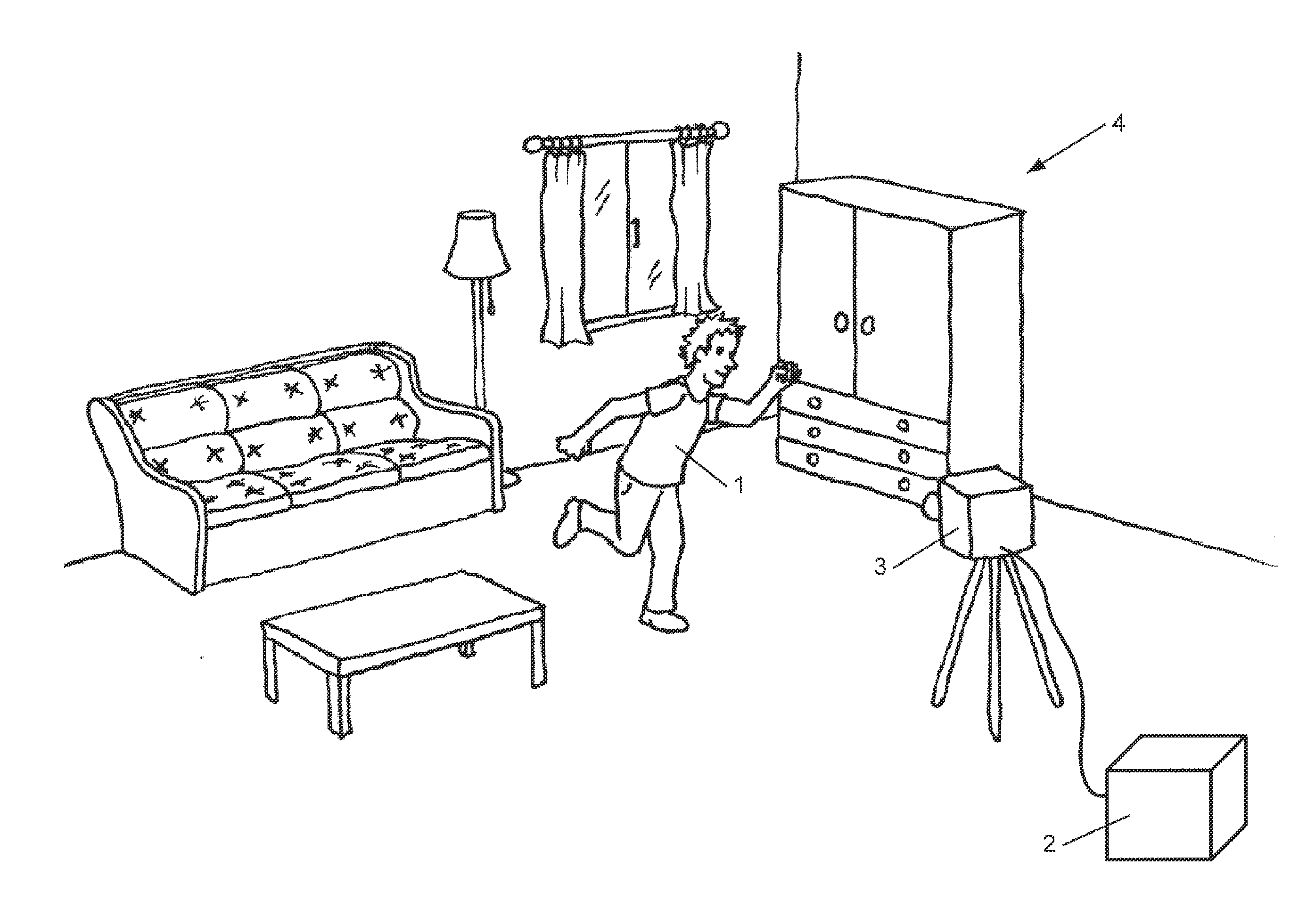
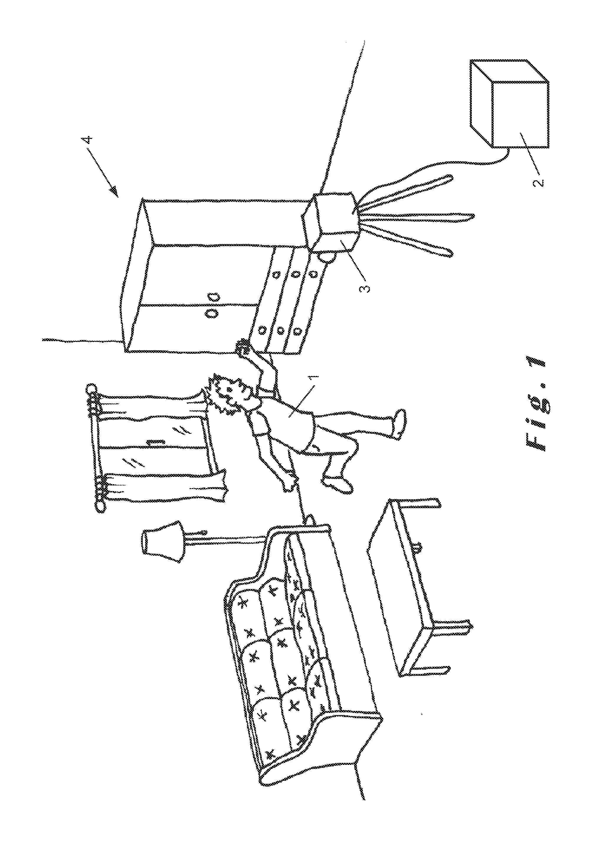
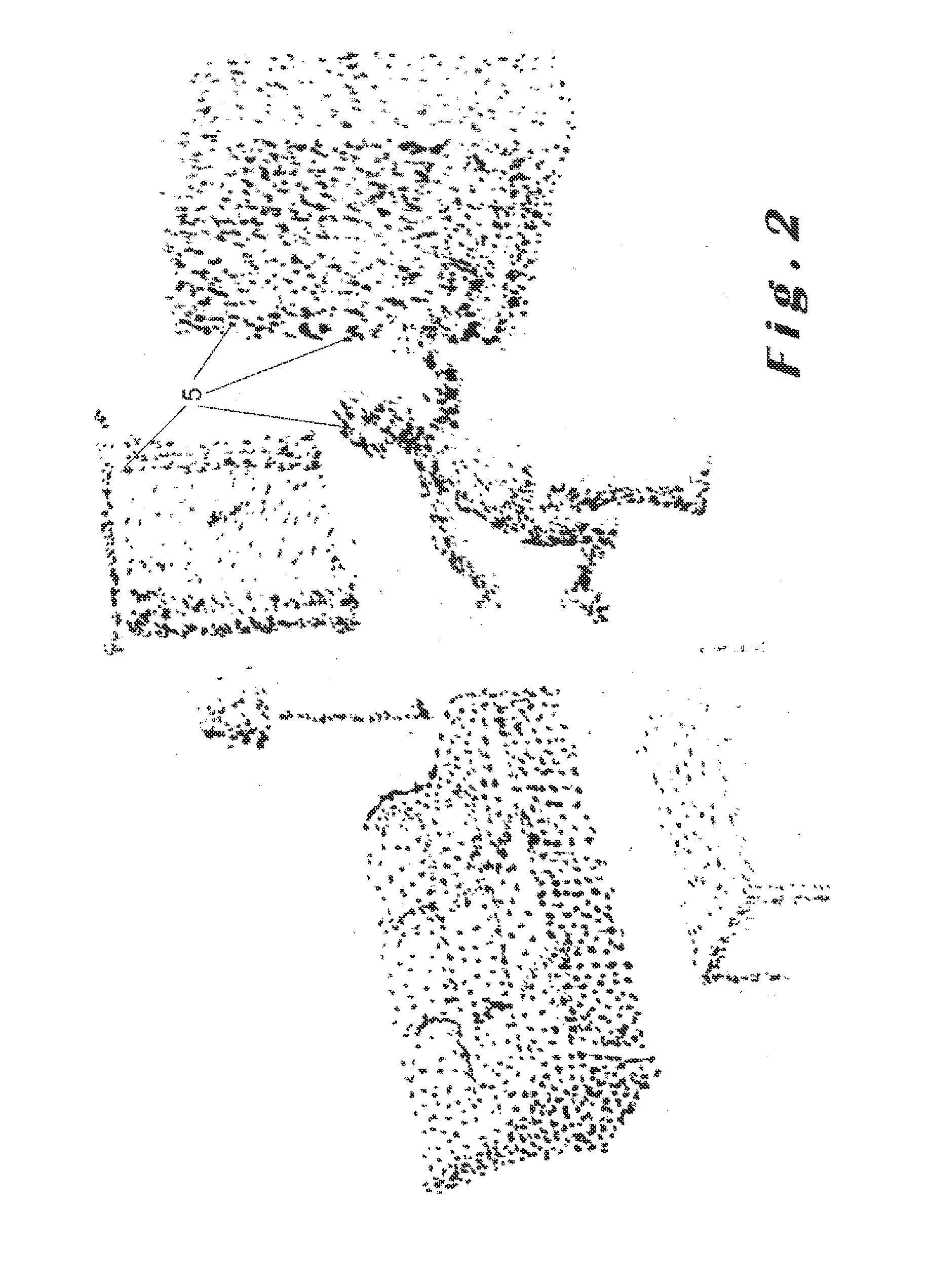
[0064]In a first embodiment, the depth of the three-dimensional cloud of points 5 corresponding to the body of the user 1 is then averaged. This may be carried out in at least two alternative manners:

[0065]In the first alternative of this first embodiment, if a cluster of points 5 has been identified as corresponding to the body of the user, using for instance the method disclosed in International Patent Application WO 2008 / 128568 A1, the depth of the centroid of this cluster of points 5 will be considered as the average depth of the body of the user 1 in the image.

[0066]In the second alternative of this first embodiment, the depth of the points 5 representing the user 1 in the depth map (Indg) can be averaged. For example, the following equation may be used:

dav=∑i=1n∑j=1mIndg(i,j)·Ib(i,j)

wherein dav is the arithmetic mean depth, and n and m are the dimensions of the depth map image. Instead of an arithmetic mean, a different type of average, such as, for instance, the median, may b...

second embodiment

[0076]In a second embodiment, instead of calculating the dimensions a and b of the elliptical mask 7 on the basis of the average depth dav, the individual depth d(i,j) of each one of the pixels in the dilated contour image (Id) may instead be considered for the dimensions of the elliptical mask 7 to be applied for each individual pixel. This may be carried out, for example, using a dilated contour depth map (Ie)=(Id)·(Indg) and the equations:

a(i,j)=Fd(i,j)·Ab(i,j)=Fd(i,j)·B

[0077]In both embodiments, the final result is an accumulator array as depicted in FIG. 7, wherein the intensity peaks 8 are in the positions where the possibility of the occurrence of a human head in the source image is highest. However, due to the eventual presence of the extremities of the user 1 in the source image, resulting into nearly parallel lines in the contour image (Ic), FIG. 7 may also present, apart said intensity peaks 8, intensity ridges 9 (FIG. 8) corresponding to these extremities. In order to su...


PUM


Abstract

Described herein is a method for recognising a human head in a source image. The method comprises detecting a contour of at least part of a human body in the source image, calculating a depth of the human body in the source image. From the source image, a major radius size and a minor radius size of an ellipse corresponding to a human head at the depth is calculated, and, for at least several of a set of pixels of the detected contour, generating in an accumulator array at least one segment of an ellipse centred on the position of the contour pixel and having the major and minor radius sizes. Positions of local intensity maxima in the accumulator array are selected as corresponding to positions of the human head candidates in the source image.

Description

TECHNICAL FIELD[0001]The present invention relates to a method and a computer system for the recognition of a human head in a source image. In particular, the present invention relates to a method of using depth information for predicting the most probable perceived size of the human head so as to assist in its recognition.BACKGROUND OF THE INVENTION[0002]In various imaging systems and image treatment applications, it is advantageous to automatically recognise the position and / or the orientation of a human head in a source image. For instance, a user may interact with a program running in a computer system, for example, a videogame program, by moving his head within the range of an imaging device. Alternatively, such a head recognition method may also be used in an imaging device for adjusting parameters such as aperture, exposure time, focus depth, etc. so as to optimize them for portraiture.[0003]Interaction with computer systems, and, in particular the input of data and commands,...

Claims


Application Information

Patent Timeline
IPC IPC(8): G06K9/34G06K9/46G06K9/00
CPCG06K9/00234G06K9/00201G06V40/162G06V20/64G06T7/60G06V10/40
Inventor BAELE, XAVIERTHOLLOT, JULIENMARTINEZ GONZALEZ, JAVIERSIMONS, KEVIN
Owner SOFTKINETIC SOFTWARE
Learn More