Fuel cell cooling system with coupling out of heat

a fuel cell and heat coupling technology, applied in the field of cooling systems, can solve the problems of limited flow of cooling air that can be achieved in passenger vehicles, speed-dependent flow of cooling air, and difficulty in cooling fuel cell vehicles at nominal load under extreme environmental conditions, so as to relieve the load on the fuel cell cooling circuit, and reduce the effect of fuel cell cooling circuit load

Active Publication Date: 2013-01-24
ROBERT BOSCH GMBH
View PDF9 Cites 37 Cited by
  • Summary
  • Abstract
  • Description
  • Claims
  • Application Information

AI Technical Summary

Benefits of technology

[0007]This has the advantage that it is possible to relieve the load on the fuel cell cooling circuit, in particular temporarily, in borderline situations for the cooling capacity, e.g. when traveling uphill or when traveling for relatively long distances at maximum speed in conditions encountered in hot countries, e.g. at an ambient temperature of 45° C. This in turn has the advantage that there is the possibility of not throttling the motive power, or at least throttling it only at a later point, in borderline situations for the cooling capacity, in particular in order to protect the fuel cell system from overheating.
[0036]In order to counteract or delay a rise in the temperature of the battery, the capacity of the cooler and / or of the chiller of the battery cooling circuit can be increased and / or the capacity of the heater of the accumulator cooling circuit can be reduced.

Problems solved by technology

Although the permissible maximum operating temperature of low-temperature polymer electrolyte fuel cells has risen significantly in the last few years and is currently around 90° C., cooling fuel cell vehicles at nominal load under extreme environmental conditions is still a challenge.
Usually, however, the flows of cooling air that can be achieved in a passenger vehicle are speed-dependent and are limited by the shape of the body, packaging etc.

Method used


Image

  • Fuel cell cooling system with coupling out of heat
  • Fuel cell cooling system with coupling out of heat

Examples


Embodiment Construction

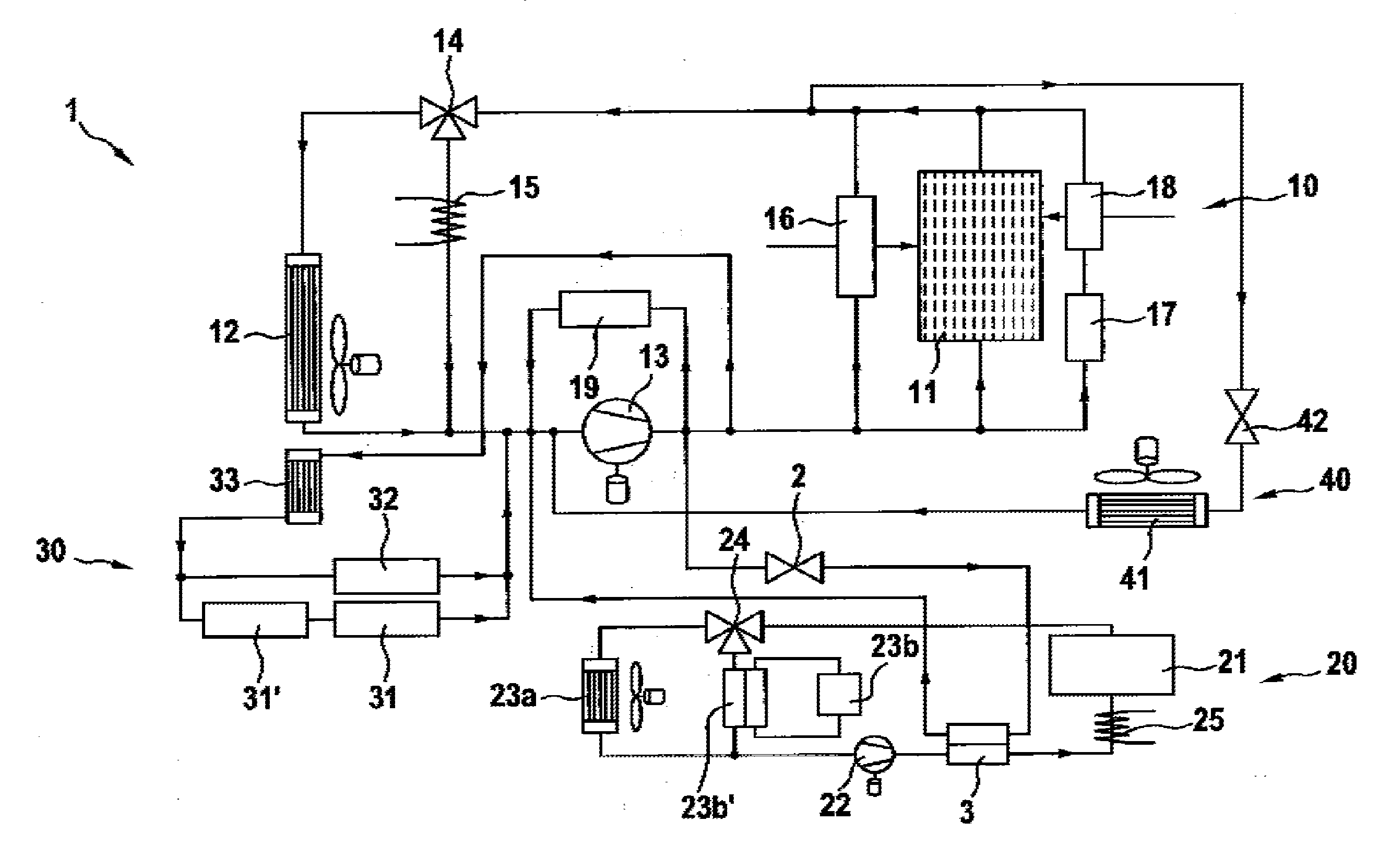
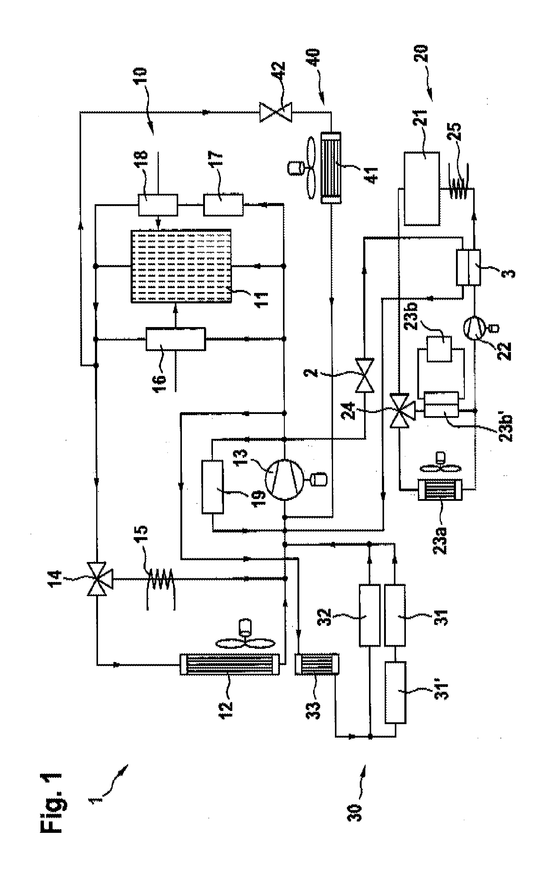
[0044]FIG. 1 shows that the cooling system 1 comprises a fuel cell cooling circuit 10 for cooling the fuel cell system 11 and a battery cooling circuit 20 for cooling a battery 21, in which thermal energy can be exchanged between the fuel cell cooling circuit 10 and the battery cooling circuit 20 and, in particular, can be coupled from the fuel cell cooling circuit 10 into the battery cooling circuit 20. In particular, the battery 21 can be a traction battery or an electric traction accumulator, e.g. a nickel metal hydride battery or a lithium ion battery. In particular, the fuel cell cooling circuit 10 can be the main cooling circuit of a vehicle.

[0045]In order to regulate the flow of heat in terms of time and in terms of quantity, a valve 2, in particular a controllable valve, is provided between the fuel cell cooling circuit 10 and the battery cooling circuit 20. For example, this can be a shutoff valve or a thermostat based on an expanding material. The valve 2 is used, in parti...


PUM

PropertyMeasurementUnit
temperatureaaaaaaaaaa
temperaturesaaaaaaaaaa

Abstract

A cooling system (1) for a fuel cell system (11), in particular for a vehicle, which comprises a fuel cell cooling circuit (10) for cooling the fuel cell system (11), and a battery cooling circuit (20) for cooling a battery (21), with an exchange of thermal energy between the fuel cell cooling circuit (10) and the battery cooling circuit (20).

Description

BACKGROUND OF THE INVENTION[0001]The present invention relates to a cooling system for a fuel cell system, to an operating method and to a correspondingly equipped vehicle.[0002]Research on motor vehicles with fuel cell drive systems (FCV: “Fuel Cell Vehicle”; FCHV: “Fuel Cell Hybrid Vehicle”) has been in progress for several years. DE 101 42 923 A1, for example, describes a drive assembly for a vehicle driven by a fuel cell and an internal combustion engine.[0003]For use in motor vehicles with a fuel cell drive system, low-temperature polymer electrolyte fuel cells (NT-PEM fuel cells) are employed, in particular. Although the permissible maximum operating temperature of low-temperature polymer electrolyte fuel cells has risen significantly in the last few years and is currently around 90° C., cooling fuel cell vehicles at nominal load under extreme environmental conditions is still a challenge. Since low-temperature polymer electrolyte fuel cells customarily have only a comparative...

Claims


Application Information

Patent Timeline
Patent Type & Authority Applications(United States)
IPC IPC(8): H01M8/04
CPCH01M10/5004H01M10/5006H01M10/5016H01M10/5077Y02E60/50H01M10/5093H01M8/04007H01M8/04067H01M8/04708H01M10/5079H01M10/625H01M10/615H01M10/6568H01M10/6569H01M10/66H01M10/613H01M16/006Y02E60/10
Inventor VOLLMER, DIRKPFEIL, OLIVER
Owner ROBERT BOSCH GMBH
Why Eureka
Try Eureka