Surgical manipulation and occlusion device

a technology of uterine manipulation and occlusion device, which is applied in the field of surgical instruments for moving and positioning the uterus, can solve the problems of less ability to move to the right or left, more complications, and surgery without uterine manipulators, so as to prevent the leakage of pneumoperitoneum, and minimize the movement of the vaginal occlusion

Inactive Publication Date: 2013-01-24
QUIMBY JENNIFER C
View PDF24 Cites 31 Cited by
  • Summary
  • Abstract
  • Description
  • Claims
  • Application Information

AI Technical Summary

Benefits of technology

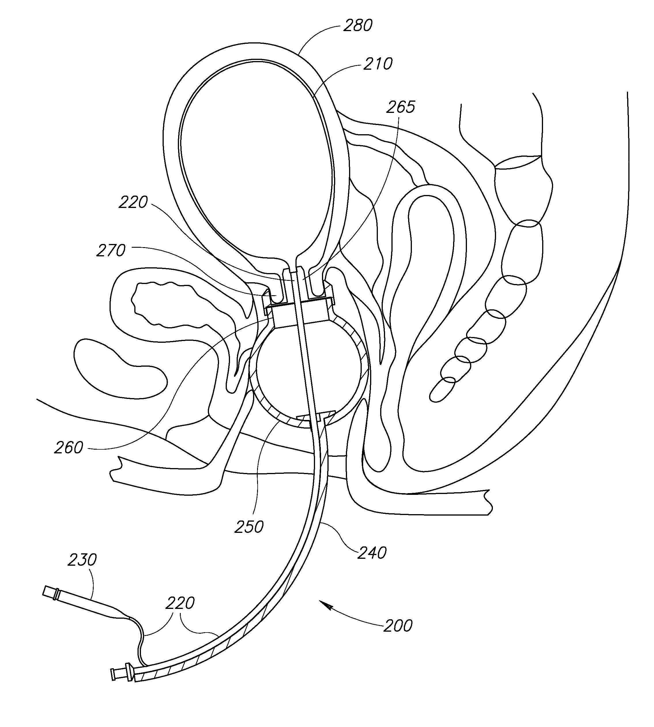
[0027]Certain aspects provide a vaginal occlusion device, comprising in combination: a vaginal occlusion portion comprising a resilient deformable member (e.g., bulb, cone, cylinder, etc.) having a channel therethrough having a proximal opening sized to fit, during use of the device, snuggly against a manipulation rod or tube, and a relatively larger distal opening suitable to provide for angular and / or rotational movement of the rod or tube passing through the member via the distal and proximal openings while minimizing movement of the vaginal occlusion member when the tube is subjected to manipulation, and wherein the member is suitably configured to fit snugly against the contours of an inner vaginal tissue surface, and a cervical fitting member configured to, in use of the device, engage and secure a cervix. In particular embodiments, in use of the device, the vaginal occlusion portion is axially slidably positionable away from the cervical fitting member along the rod or tube. In certain aspects, at least a part of the tubing portion is rigid. In particular embodiments, the cervical fitting member is configured to fit snugly against the cervix and secure the cervix. In preferred embodiments, securing the cervical fitting member occurs via barb means, wherein the barb means are configured to preclude or retard slipping or rotating of the cervical fitting member relative to the cervix. In certain aspects, the resilient deformable member generally comprises at least one shape selected from the group consisting of a sphere, a cylinder, a cone, a torus, a bulb, and a wheel.
[0028]Additional aspects provide a uterine manipulator suitable for laparoscopic surgical procedures, comprising: a vaginal occlusion portion comprising a resilient deformable member (e.g., bulb, cone, cylinder, etc.) having a channel therethrough having a proximal opening sized to fit, during use of the device, snuggly against a manipulation rod or tube, and a relatively larger distal opening suitable to provide for angular and / or rotational movement of the rod or tube passing through the member via the distal and proximal openings while minimizing movement of the vaginal occlusion member when the tube is subjected to manipulation, and wherein the member is suitably configured to fit snugly against the contours of an inner vaginal tissue surface; a cervical fitting member configured to be securable, in use, to a cervix; a balloon at a distal trans-cervical end of a tubing portion that extends through the vaginal occlusion element and the cervical fitting element, the tubing in fluid communication between a fluid inlet at a proximal exterior end and the balloon to enable intrauterine inflation of the balloon with a fluid, wherein the vaginal occlusion element is positioned or positionable along the tubing portion between the cervix and the vagina to provide for a snug fit with the vagina, thereby preventing leakage of pneumoperitoneum during a surgical procedure. In certain embodiments, securing the cervical fitting member occurs via barb means, wherein the barb means are configured to preclude or retard slipping or rotating of the vaginal occlusion device relative to the cervix. In particular aspects, the deployment of the barbs allows for a secure fitting tight up against and / or within the cervix. In certain embodiments, a proximal exterior end of the device comprises a handle, and in certain aspects, the handle is in mechanical communication with the cervical fitting member. In particular embodiments, the handle is configured to deploy or otherwise manipulate or position the barb means of the cervical fitting member, wherein the barb means prevent or retard slipping or rotating of the device from placement, and wherein, the handle is in mechanical communication with the cervical fitting member. In certain aspects, the deployment of the barb means is controlled by a switch or a spring. In certain embodiments, the resilient deformable member comprises the shape of at least one shape selected from the group consisting of a cylinder, a cone, a torus, a bulb, and a wheel. In certain aspects, the surgery comprises laparoscopic surgery (e.g., hysterectomy).
[0029]Further provided is a vaginal occlusion device, comprising: a vaginal occlusion portion comprising a resilient deformable member (e.g., bulb, cone, cylinder, etc.) having a channel therethrough having a proximal opening sized to fit, during use of the device, snuggly against a manipulation rod or tube, and a relatively larger distal opening suitable to provide for angular and / or rotational movement of the rod or tube passing through the member via the distal and proximal openings while minimizing movement of the vaginal occlusion member when the tube is subjected to manipulation, and wherein the member is suitably configured to fit snugly against the contours of an inner vaginal tissue surface. In certain aspects the vaginal occlusion device is in combination with a cervical fitting member suitable to secure a cervix and a uterine manipulation rod or tube. In particular aspects, the vaginal occlusion portion is positionable along the rod or tube. In certain embodiments, at least a part of the rod or tubing portion is rigid. In certain embodiments, the cervical fitting member is configured to fit snugly against the cervix and secure the cervix using barb means. In particular aspects, securing the cervical fitting member occurs via barbs, wherein the barbs are configured to preclude or retard slipping or rotating of the vaginal occlusion device relative to the cervix. In certain embodiments, the resilient deformable member comprises a shape selected from at least one from the group consisting of a cylinder, a cone, a torus, a bulb, and a wheel.
[0030]Additionally provided are methods for conducting surgery, comprising: obtaining a vaginal occlusion portion comprising a resilient deformable member (e.g., bulb, cone, cylinder, etc.) having a channel therethrough having a proximal opening sized to fit, during use of the device, snuggly against a manipulation rod or tube, and a relatively larger distal opening suitable to provide for angular and / or rotational movement of the rod or tube passing through the member via the distal and proximal openings while minimizing movement of the vaginal occlusion member when the tube is subjected to manipulation, and wherein the member is suitably configured to fit snugly against the contours of an inner vaginal tissue surface; and positioning, within a patient's vagina, the vaginal occlusion element between the cervix and the vaginal opening to provide for a snug fit within the vagina, wherein maintaining insufflation of the patient's abdomen during a surgical procedure is afforded, wherein such that the abdomen of the patient remains insufflated. In certain aspects, the method further comprises the use of a cervical fitting member in combination with the vaginal occlusion element, wherein the cervical fitting member is capable of being affixed to the cervix via barb means to preclude or retard slipping or rotating of the uterine occlusion element relative to the cervix. In certain aspects, the method further comprises deployment of the barb means of the cervical fitting member, wherein the cervical fitting member is prevented from slipping or rotating from the cervix. In certain embodiments, deployment of the barb means of the cervical fitting member allows for snug fitting which prevents slipping or rotating without stitching the cervical fitting portion into the cervix. In certain aspects, the surgery comprises laparoscopic surgery. In particular embodiments, the surgery comprises hysterectomy.

Problems solved by technology

The most feared complications when performing a hysterectomy (removal of uterus) by any route of approach are potential urinary tract lesions including bladder, and particularly the ureters.
Total laparoscopic hysterectomy (HTL) is a significant challenge for laparoscopic surgeons because the surgery is technically difficult, demanding, and often is accompanied by prolonged surgical time, thereby making the incidence of complications is greater.
Surgery without a uterine manipulator is more dangerous and can be more time consuming.
The capability for movement to the right or left is minimal, and pelvic tissues and organs are unnecessarily stressed by application of excessive torque.
Exposure of the vital regions of the pelvis is difficult, and surgery with such instruments is often suboptimal or even unsafe.
Further, such devices and methods routinely require an extra staff member to maintain the instrument in the correct position to perform a procedure.
In some cases this is very cumbersome, and obviously adds time and cost to the procedure.
Another potential complication is uterine perforation resulting from excessive force being exerted by the physician when trying to place the manipulator into the uterus or during attempted manipulation of the uterus for better visualization.
However, this device has the disadvantage that it is simply a silastic tube in which one of its edges serves to demarcate the edge of the fascia to carry out the colpotomy (incision) and to prevent leakage of pneumoperitoneum, but said device does not secure the cervix and uterus and allow for manipulation of the uterus, so that it does not facilitate the procedure because it fails to provide an optimal view of the vulnerable structures, which disadvantage is more evident in large uteri.
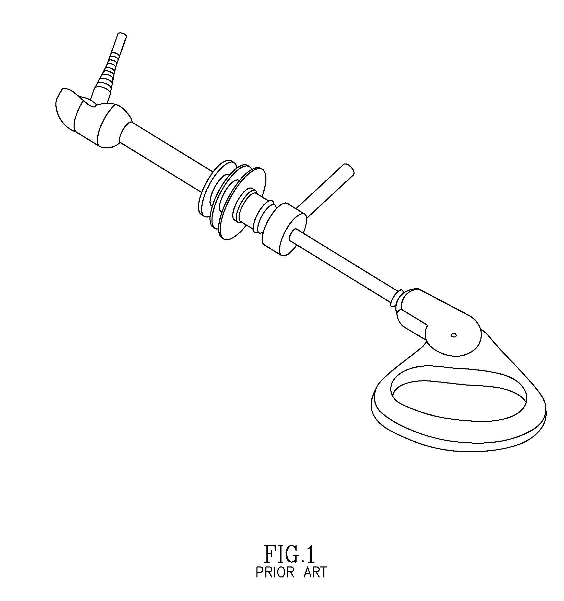
In addition, the valve whose function is to prevent gas from leaking from the abdomen, in practice does not prevent this leakage, and moreover the annular external ribs (shown as element 132 in FIG. 2 herein) are also not adequate for this purpose.
However, this uterine manipulator has the disadvantage that it is very large and difficult to maneuver, and for the exposure of the fascia it has a rotary latch instead of a complete cap, so the exposure and protection of structures such as the bladder and uterine vessels may be insecure and not uniform.
In addition, the three soft rings do not adequately prevent gas escaping from the abdomen because they are rigidly attached to the device and therefore they do not allow the physician to manipulate the device as required during surgery without the rings moving from the places of contact within the vagina and thus allow gas to escape.
It is an instrument primarily designed for mobilizing the uterus, and has very fragile elements so its use to remove large uterus is very difficult.
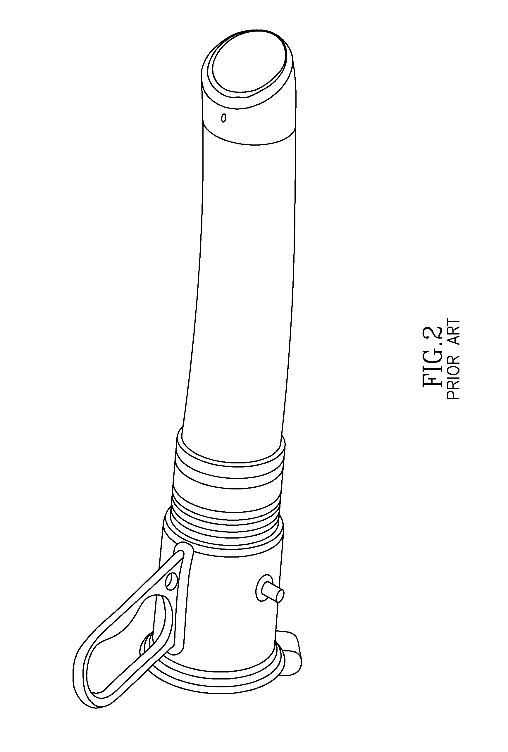
In addition, the inflatable silicone ring (43 shown in FIG. 3 herein) is rigid and attached at its base across the entire width of the ring base such that angular movement of the device, being immediately transferred to the ring, tend to break the seal allowing loss of insufflation, and thus does not adequate occlude the vagina.
This manipulator has the disadvantage that it is completely straight and lacks of articulation in the cap area so that no anteflexion and no 90 degree movements are available, hence in some difficult patients and in certain technical difficulty circumstances, the access to the rear of the fascia can be very difficult or even dangerous.
One of the most significant complications of the aforementioned type of manipulators is that upon a few surgical cuts around the uterus, so that the uterus can be removed, the gas that was used to insufflate the abdomen rushes out of the vagina.
This results in reducing the ability of the surgeon to complete the hysterectomy.
Although progress has been made in the art as noted above, all existing uterine manipulators known to the inventor possess significant disadvantages and limitations, including maintaining sufficient insufflation of the abdomen during laparoscopic hysterectomies.

Method used


Image

  • Surgical manipulation and occlusion device
  • Surgical manipulation and occlusion device
  • Surgical manipulation and occlusion device

Examples


Embodiment Construction

[0046]All references cited herein are incorporated by reference in their entirety as though fully set forth. Unless defined otherwise, technical and scientific terms used herein have the same meaning as commonly understood by one of ordinary skill in the art to which this invention belongs. Singleton et al., Dictionary of Microbiology and Molecular Biology 3rd ed., J. Wiley & Sons (New York, N.Y. 2001); March, Advanced Organic Chemistry Reactions, Mechanisms and Structure 5th ed., J. Wiley & Sons (New York, N.Y. 2001); and Sambrook and Russell, Molecular Cloning: A Laboratory Manual 3rd ed., Cold Spring Harbor Laboratory Press (Cold Spring Harbor, N.Y. 2001), provide one skilled in the art with a general guide to many of the terms used in the present application.

[0047]One skilled in the art will recognize many methods and materials similar or equivalent to those described herein, which could be used in the practice of the present invention. Indeed, the present invention is in no way...


PUM


Abstract

Provided are uterine manipulators comprising in combination: a vaginal occlusion portion comprising a resilient deformable member (e.g., bulb, cone, cylinder, etc.) having a channel therethrough having a proximal opening sized to fit, during use of the device, snuggly against a manipulation rod or tube, and a relatively larger distal opening suitable to provide for angular and/or rotational movement of the rod or tube passing through the member via the distal and proximal openings while minimizing movement of the vaginal occlusion member when the tube is subjected to manipulation, and wherein the member is suitably configured to fit snugly against the contours of an inner vaginal tissue surface; and a cervical fitting portion which is securable to the cervix. Also provided are surgical methods using said elements to provide for a snug fit with the cervix while sealing the vagina, wherein maintaining abdominal insufflation during surgery is afforded.

Description

CROSS-REFERENCE TO RELATED APPLICATIONS[0001]This application claims the benefit of priority to U.S. Provisional Patent Application Ser. No. 61 / 510,008 filed 20 Jul. 2011, which is incorporated by reference herein in its entirety.FIELD OF THE INVENTION[0002]Aspects of the invention relate generally to medical devices, and more particularly to surgical instrumentation for moving and positioning a uterus for better visualization and access during surgery. Additional aspects relate to such surgical instrumentation that additionally occludes the vagina to prevent loss of insufflation during surgery. Further aspects relate to surgical methods as described herein.BACKGROUND[0003]The most feared complications when performing a hysterectomy (removal of uterus) by any route of approach are potential urinary tract lesions including bladder, and particularly the ureters. The incidence of urinary tract injury in laparoscopic hysterectomy is about 0.02-1.7%, primarily arising during securing of ...

Claims


Application Information

Patent Timeline
Patent Type & Authority Applications(United States)
IPC IPC(8): A61B17/42
CPCA61B17/4241A61B2017/00349A61B2017/0042A61B2017/3419A61B2017/00991A61B2017/22069A61B2017/00477
Inventor QUIMBY, JENNIFER C.
Owner QUIMBY JENNIFER C
Why Eureka
Try Eureka