Apparatus for treating substrates

a technology for treating substrates and apparatuses, applied in the direction of electrolysis components, vacuum evaporation coatings, coatings, etc., can solve the problems of requiring regular maintenance, closing, and least minimising these frequent and laborious maintenance cycles, so as to minimise the number of components required, minimise the effect of unnecessary wear and tear of the power connection and regular and efficient pre-treatment process

Active Publication Date: 2013-01-31
BOBST MANCHESTER LTD
View PDF10 Cites 1 Cited by
  • Summary
  • Abstract
  • Description
  • Claims
  • Application Information

AI Technical Summary

Benefits of technology

[0010]This configuration is particularly advantageous because it allows the pre-treatment to occur with the benefits of removing moisture and other contaminants which may be present on a substrate as the particles are removed by the method of sputtering. It avoids or at least minimises potential down times due to arcing and associated short circuits. It also increases the number of nucleation sites which will result in an improvement in the subsequent coating process. The coating is therefore homogeneous and with fewer defects than would otherwise be the case without such a pre-treatment.
[0025]In a further subsidiary aspect, said electrode incorporates channels for circulation of cooling liquid. These configurations are particularly advantageous because they allow the plasma affected areas to be cooled while allowing the treater to be relatively compact.

Problems solved by technology

Unfortunately, the treater of the prior art has a number of drawbacks.
It requires regular maintenance after a period of process due to the electrode tube being “dirtied” by the plasma deposits.
These deposits can cause arcing which can result in the closing down of the power supply units which incorporate means for detecting this condition.
One of the problems which the inventive concept addresses is how to avoid or at least minimise these frequent and labour intensive maintenance cycles.

Method used


Image

  • Apparatus for treating substrates
  • Apparatus for treating substrates
  • Apparatus for treating substrates

Examples


Embodiment Construction

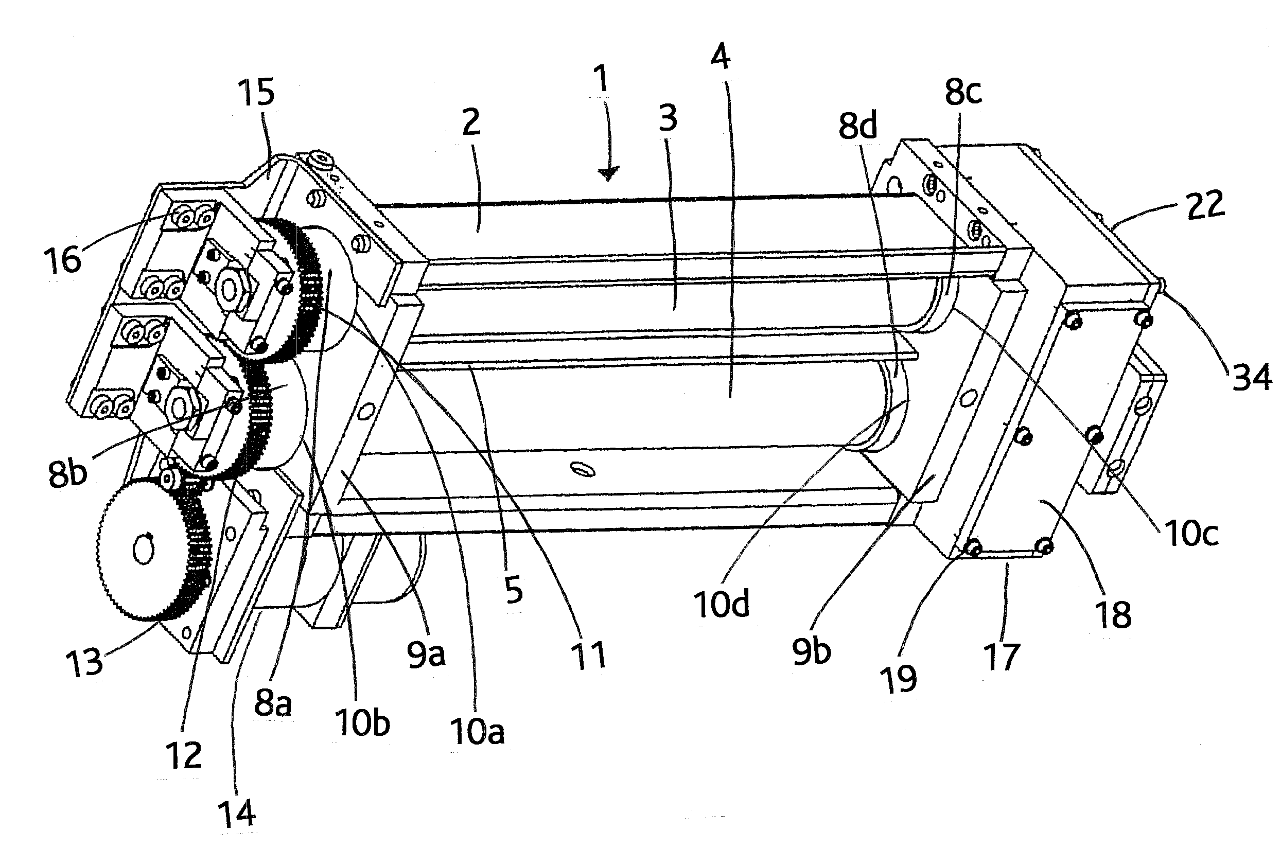
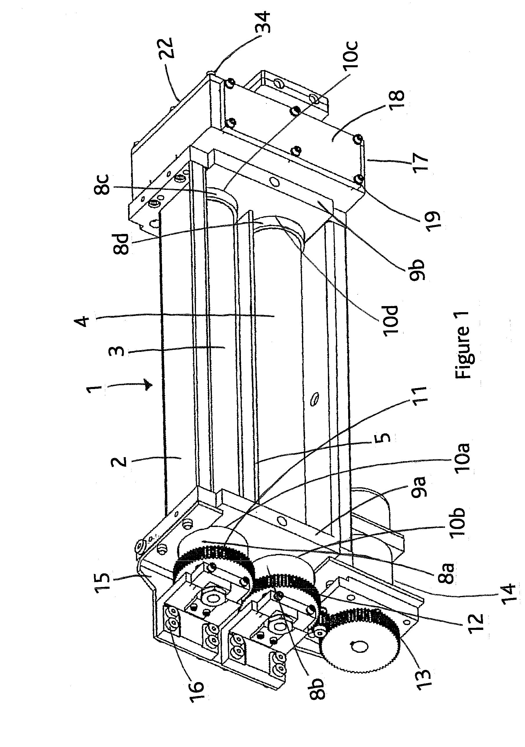
[0045]FIG. 1 shows a treater generally referenced 1. The treater 1 incorporates an aluminium extrusion body 2 with an internal W-shaped in cross-section configuration in order to accommodate cylindrical electrodes 3 and 4 in respective cavities. Body 2 incorporates a number of cooling channels for a suitable cooling fluid to pass, such as water, in order to keep the plasma affected areas cooled. A web 5 splits the body into the two electrode receiving cavities. As can be seen in FIG. 4, the rear portion 6 and the upper portion 7 of the body are substantially flat. Seals 8a, 8b, 8c and 8d are provided at either end of the electrode. These seals may take the form of a ceramic shield. The respective seals are supported in respective blocks 9a and 9b incorporating mating cylindrical bearing surfaces 10a, 10b, 10c and 10d.

[0046]Each electrode is connected and rotatable with a gear such as gear 11 and gear 12. Gears 11 and 12 incorporate a plurality of teeth which are suitable for being ...


PUM

PropertyMeasurementUnit
magnetic fieldaaaaaaaaaa
pressure levelaaaaaaaaaa
pressureaaaaaaaaaa

Abstract

Apparatus for coating a substrate with a material in a chamber subject, during use, to substantial evacuation, which includes a coating station within the chamber for coating a substrate by sputtering and / or by evaporation; at least one treating station disposed in serial with the coating station and equipped with a plasma treater incorporating a plasma generator in sufficient proximity to the substrate to treat the substrate; a magnetic device for generating a magnetic field; at least one cylindrical electrode surrounding the magnetic device, the plasma treater incorporates a device for rotating the electrode about its longitudinal axis.

Description

CROSS REFERENCE TO RELATED APPLICATION[0001]The present application is a continuation in part of U.S. patent application Ser. No. 12 / 576,318, filed Oct. 9, 2009, which claims priority of European Application No. 08017713.2, filed Oct. 9, 2008, the contents of which are incorporated in full herein by reference.TECHNICAL FIELD[0002]The invention relates to a) an apparatus for coating a substrate with a material in a chamber subject, during use, to substantial evacuation; b) a plasma treater; and c) a method of treating a substrate in a process of coating by sputtering and / or evaporation in a chamber subject to substantial evacuation during use.BACKGROUND ART[0003]The closest prior art is the Applicant's own plasma treater which is used to prepare the surface of a substrate before submission to the coating process, and this treater is also called plasma pre-treater. This prior art plasma treater incorporates two cylindrical electrodes surrounding a magnetic means. The cylindrical elect...

Claims


Application Information

Patent Timeline
Patent Type & Authority Applications(United States)
IPC IPC(8): C23C14/58C23C14/02C23C14/34
CPCB29C59/14C23C14/564H01J37/34H01J37/32541H01J37/32568H01J37/32009
Inventor BARLOW, GARYCOPELAND, NICHOLAS
Owner BOBST MANCHESTER LTD
Why Eureka
Try Eureka