Apparatus and Method for a Liquid Cooled Shield for Improved Piercing Performance

a liquid cooled shield and shield cutting technology, which is applied in the field of plasma arc torch, can solve the problems of affecting melting the shield, and affecting so as to prolong the useful life of the shield, enhance the cut quality of the plasma arc torch, and affect the cut quality and the life of the shield.

Active Publication Date: 2013-01-31
HYPERTHERM INC
View PDF7 Cites 15 Cited by
  • Summary
  • Abstract
  • Description
  • Claims
  • Application Information

AI Technical Summary

Benefits of technology

[0010]In another aspect, the invention features a method for reducing formation of slag on a shield secured to a plasma arc torch that pierces and cuts a metallic workpiece producing splattered molten metal directed at the torch. The method can include the step of contact-cooling a first surface of the shield by a gas flow, contact-cooling a second surface of the shield by a liquid flow and providing a seal assembly to retain the liquid flow, the seal assembly configured to retain the liquid in contact with the second surface relative to a retainer cap of the plasma arc torch. The method can also include conductively cooling a third surface of the shield exposed to the splattered molten metal by providing a thermal conductive path formed at least in part of a thermally conductive material in thermal communication with the first surface and the second surface.
[0011]In yet another aspect, the invention features a method for reducing formation of slag on a shield secured to a plasma arc torch that pierces and cuts a metallic workpiece producing splattered molten metal directed at the torch. The method can include the step of rapidly cooling the shield secured to the plasma arc torch with a cooling medium flow, retaining the cooling medium flow in the plasma arc torch, and repeatedly cooling the shield (e.g., cooling the shield a plurality of times, a plurality of cycles, etc.) to prevent formation of slag on a surface of the shield exposed to the splattered molten metal.
[0026]In some embodiments, a second surface can be contact-cooled by a liquid flow, the second surface disposed relative to a first end of the shield. A shield can include a third surface exposed to splattered molten metal, and can be disposed relative to a second end of the shield. The shield can also include a flange disposed relative to the first end of the shield, at least a portion of the first surface (e.g., surface contact-cooled by a gas flow) and second surface disposed on the flange. In some embodiments, contact-cooling a second surface of a shield by the liquid flow includes providing for constant liquid flow around an outer surface of the shield.

Problems solved by technology

For example, formation / buildup of slag on the shield can affect defining an initial height of the torch, which can affect the cut quality of the plasma arc torch.
Formation of slag on a shield can also block vent holes and / or an orifice of the shield, affecting both cut quality and the life of the shield (e.g., by affecting the ability to cool the shield).
Slag formation on a shield can, in some cases, melt the shield.
Slag formation can also cause the shield to buildup heat to the point of the oxidation temperature of the shield (e.g., if the shield is made from copper, heat buildup from the slag can cause high copper temperatures that result in oxidation of the copper), thereby causing degradation of the shield (e.g., at the edges of the orifice).

Method used


Image

  • Apparatus and Method for a Liquid Cooled Shield for Improved Piercing Performance
  • Apparatus and Method for a Liquid Cooled Shield for Improved Piercing Performance
  • Apparatus and Method for a Liquid Cooled Shield for Improved Piercing Performance

Examples


Embodiment Construction

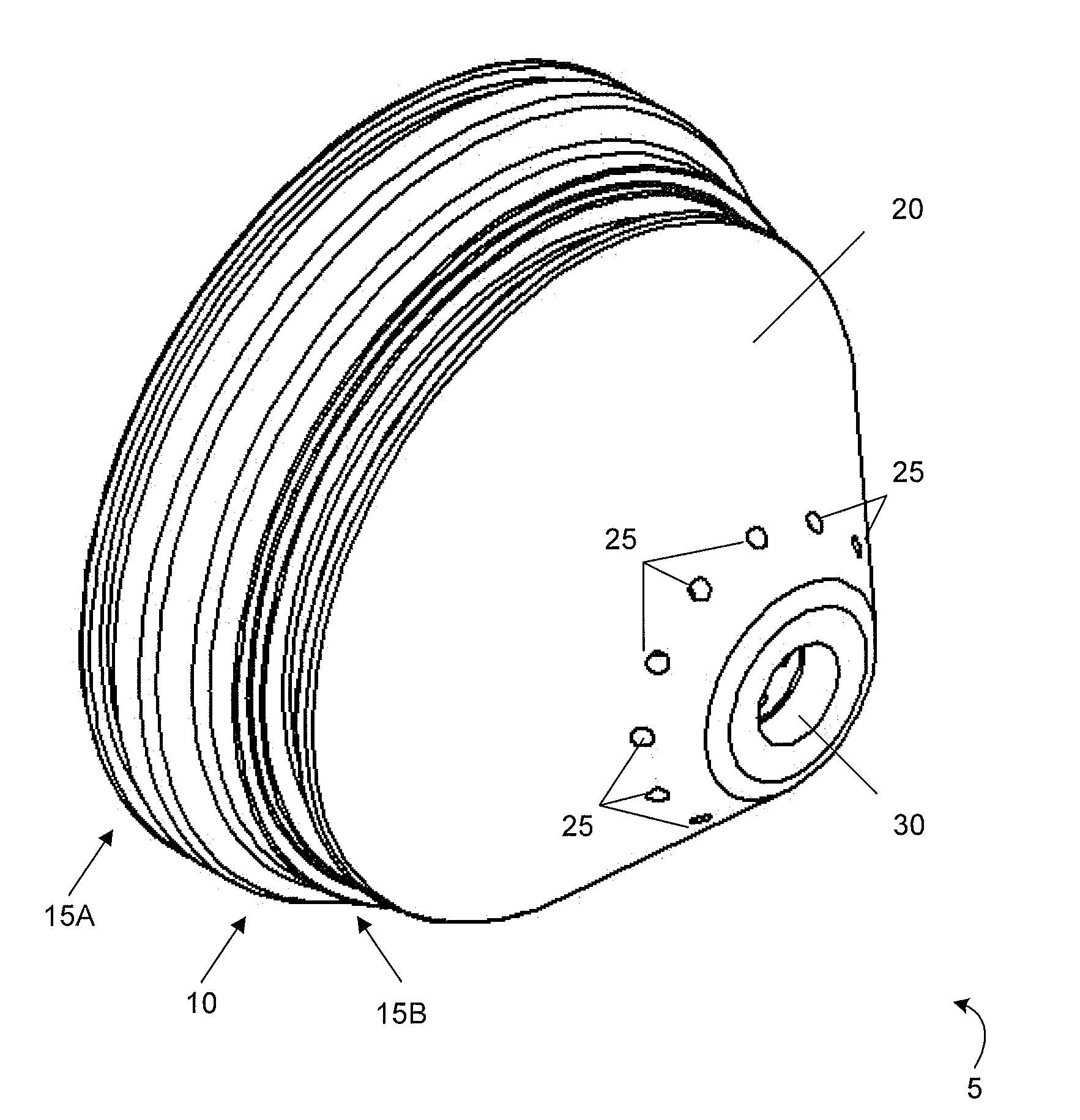
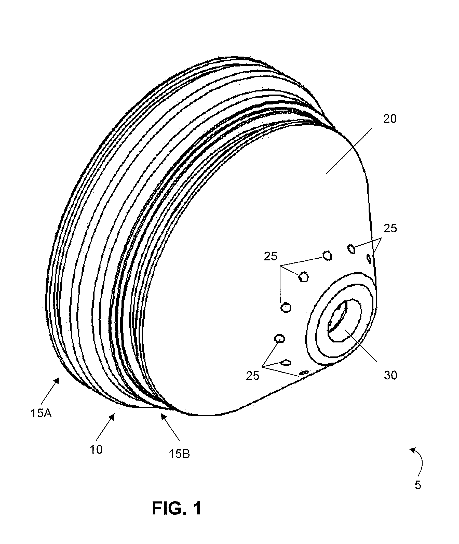
[0047]FIG. 1 is a drawing of a shield 5 according to an illustrative embodiment. The shield 5 can be disposed relative to a plasma arc torch that pierces and cuts a metallic workpiece producing a splattering of molten metal directed at the torch. The shield 5 can protect consumable components of the plasma arc torch from the splattering molten metal. The shield includes a body. In this embodiment, the body of the shield includes a first surface that is configured to be contact-cooled by a gas flow (not shown). Contact-cooling can include cooling a portion of the shield (e.g., surface) by contacting it with a coolant (e.g., cooling medium, cooling liquid, cooling gas, etc.). In some embodiments, the surface cooled by the gas flow is an internal surface (e.g., hole, exit port) disposed relative to the shield. The body of the shield also includes a second surface 10 configured to be contact-cooled by a liquid flow. In some embodiments, the body of the shield includes two pieces. In som...


PUM

PropertyMeasurementUnit
temperatureaaaaaaaaaa

Abstract

In some aspects, a retaining cap for a plasma arc torch can include a shell having an exterior surface that defines, at least in part, a first liquid coolant channel, a liner circumferentially disposed within the shell and having an interior surface that defines, at least in part, a second liquid coolant channel, and a gas flow channel defined at least in part by and located between the shell and the liner.

Description

RELATED APPLICATIONS[0001]This application is a divisional application of U.S. Ser. No. 12 / 240,157 entitled “Apparatus and Method for a Liquid Cooled Shield for Improved Piercing Performance” filed on Sep. 29, 2008, which is a CIP of U.S. Ser. No. 12 / 046,670 filed Mar. 12, 2008 (now U.S. Pat. No. 8,212,173), the contents of each of which are incorporated herein by reference in their entirety.FIELD OF THE INVENTION[0002]The invention generally relates to plasma arc torches. More specifically, the invention relates to retaining caps for securing torch components (e.g., consumables) to a plasma arc torch.BACKGROUND OF THE INVENTION[0003]Basic components of modern plasma arc torches include a torch body, an electrode (e.g., cathode) mounted within the body, a nozzle (e.g., anode) with a central orifice that produces a pilot arc to the electrode to initiate a plasma arc in a flow of a suitable gas (e.g., nitrogen or oxygen) and associated electrical connections and passages for cooling, ...

Claims


Application Information

Patent Timeline
Patent Type & Authority Applications(United States)
IPC IPC(8): H05H1/28
CPCB23K9/296B23K10/00H05H2001/3457H05H1/34F28F3/12H05H1/3457
Inventor LIEBOLD, STEPHEN M.LINDSAY, JON W.CURRIER, BRIAN J.
Owner HYPERTHERM INC
Why Eureka
Try Eureka