High-power CW fiber-laser

Inactive Publication Date: 2013-01-31
COHERENT INC
View PDF9 Cites 51 Cited by
  • Summary
  • Abstract
  • Description
  • Claims
  • Application Information

AI Technical Summary

Benefits of technology

[0015]In one aspect, laser apparatus in accordance with the present invention comprises a gain-fiber having first and second opposite ends and having a fundamental emission wavelength for laser radiation. The gain-fiber provides optical gain over a characteristic gain-bandwidth. A laser resonator is defined by the first end of the gain-fiber and a minor proximity-coupled to the second end of the gain-fiber. A first source of optical pump-radiation provides pump-radiation having a first pump-radiation wavelength. A second source of optical pump-radiation provides pump-radiation having a second pump-radiation wavelength different from the first pump-radiation wavelength. A dichroic beam combiner is provided for combining the first-wavelength and second-wavelength pump radiations. The mirror is highly reflective for wav

Problems solved by technology

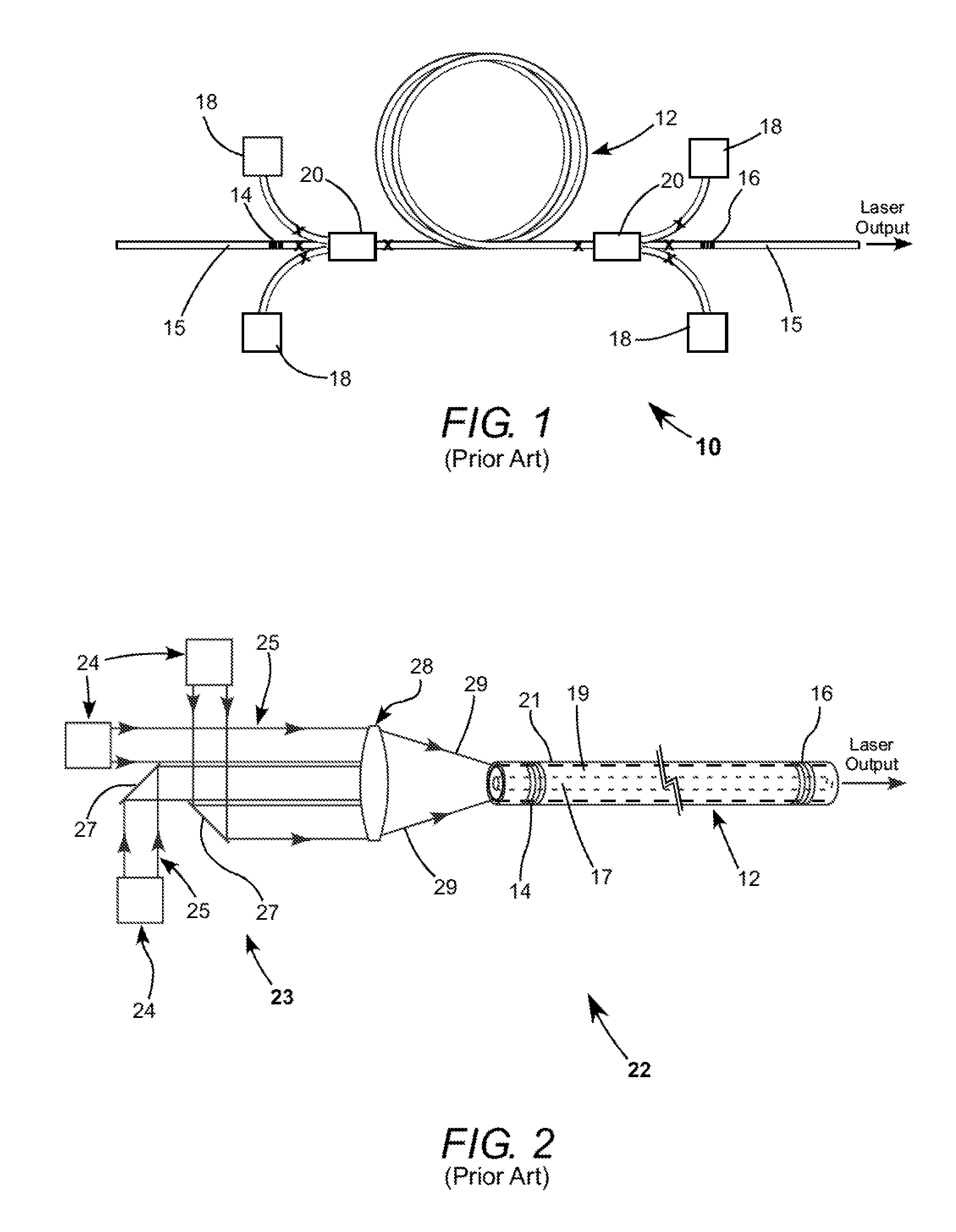
In theory at least, the output power of a fiber-laser is limited only by how much optical pumping power can be delivered into an optical gain-fiber for energizing a doped-core of the gain-fiber.
In practice, there are limits due, inter alia, to non-linear effects which can broaden the spectrum of pump radiation resulting in reduction of absorption efficiency, and photo-darkening of the fiber material which can lead to reduction of efficiency, excessive heating, and even catastrophic failure.
The non-linear effects become increasingly problematical as the gain-fiber is longer.
Fiber-splices and FBGs can be a source of instability due to transverse

Method used


Image

  • High-power CW fiber-laser
  • High-power CW fiber-laser
  • High-power CW fiber-laser

Examples


Embodiment Construction

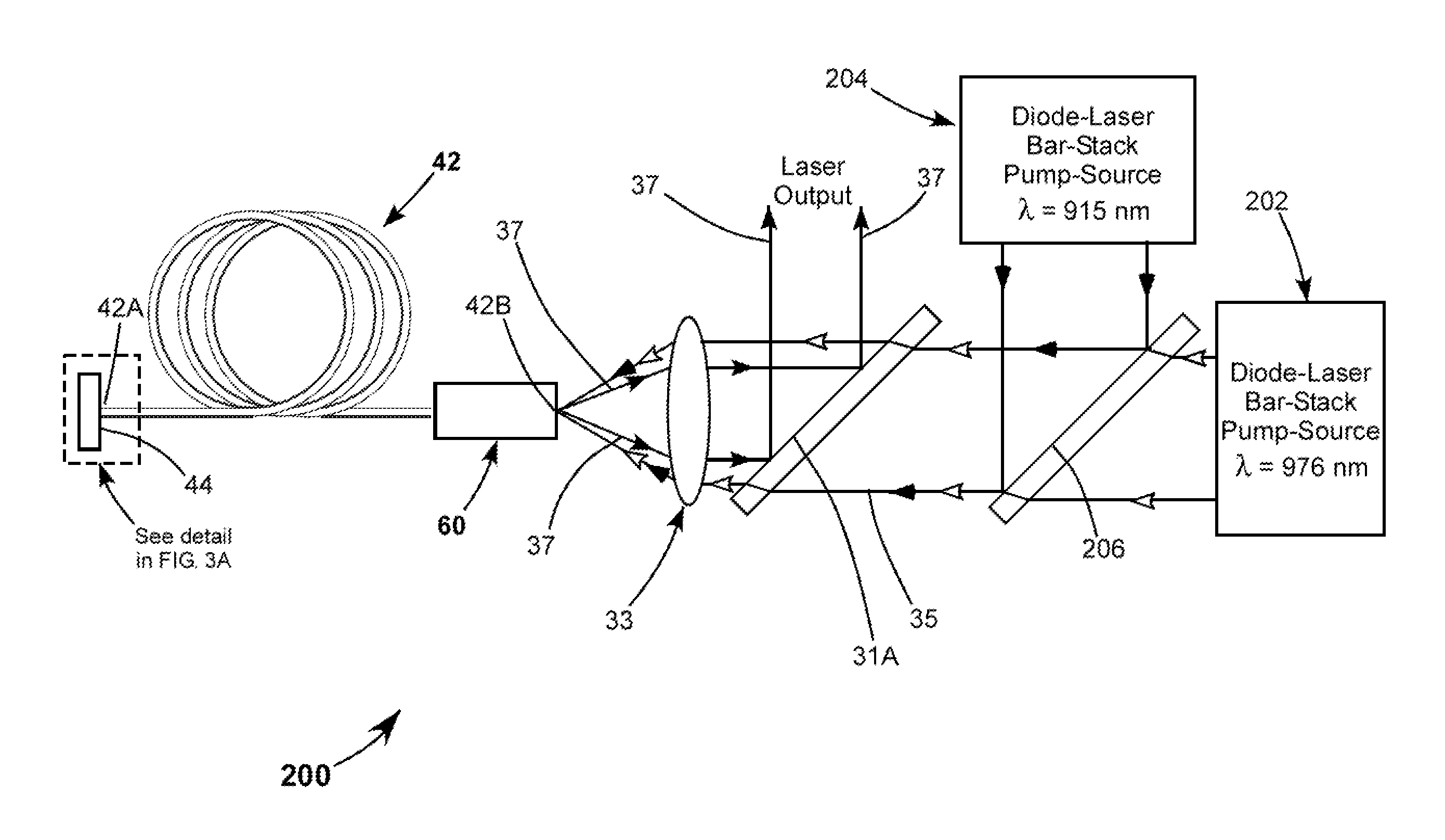
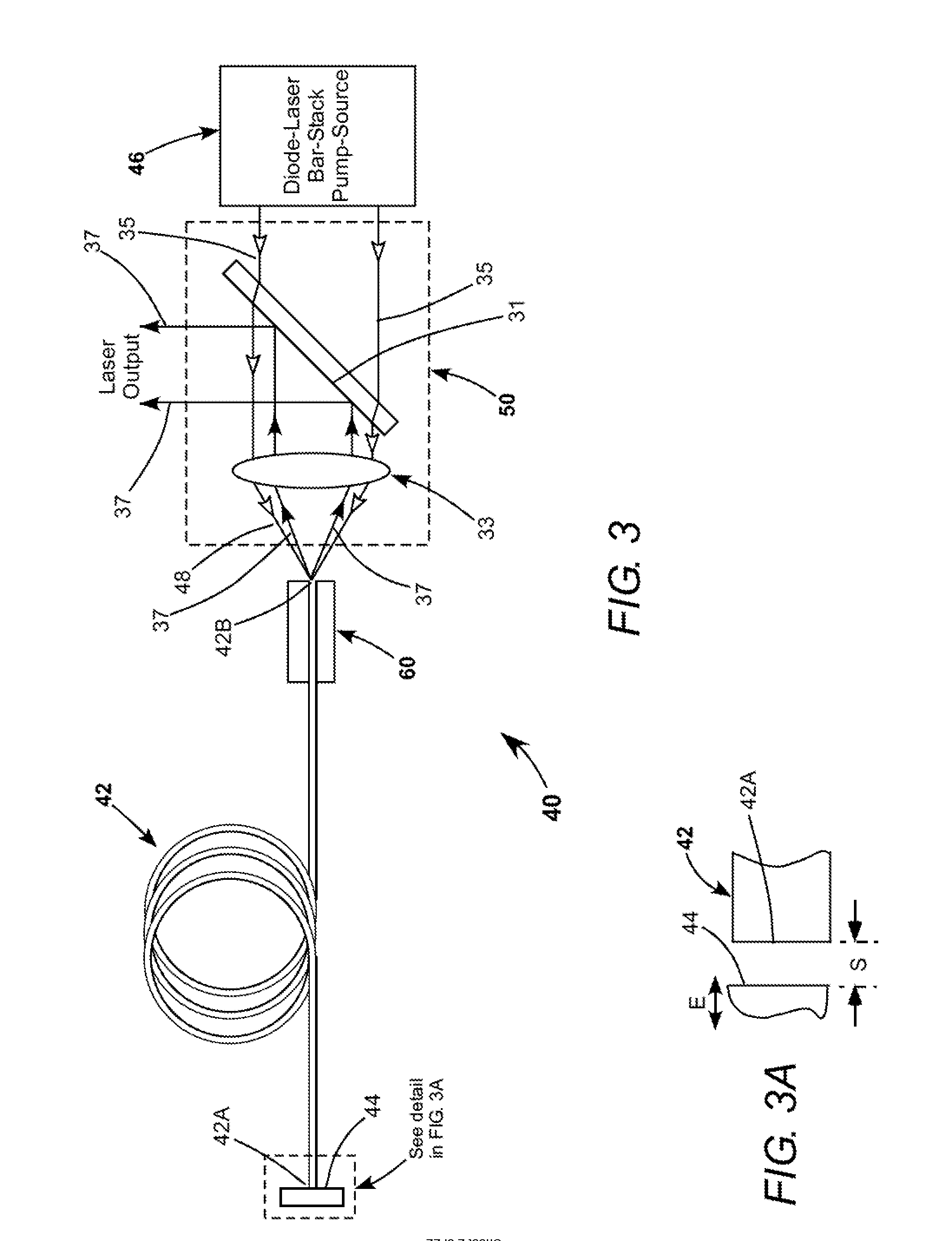
[0048]Continuing with reference to the drawings, wherein like components are designated by like reference numerals, FIG. 3 schematically illustrates a basic embodiment 40 of a fiber-laser in accordance with the present invention. Laser 40 includes a multi-mode gain-fiber 42 having a mirror 44 which is maximally reflective in the gain-bandwidth of the gain-fiber and proximity-coupled to one end 42A of the gain-fiber. The opposite end 42B of the gain-fiber is preferably left uncoated, which provides for only about 4% reflectivity, not significantly wavelength selective. This low reflectivity provides a very high (96%) output-coupling percentage for a resonator formed between mirror 44 and the uncoated end of the gain-fiber. In the inventive fiber-laser, output-coupling greater than 90% is preferred.

[0049]Pump-radiation for gain-fiber 42 is supplied by a diode-laser bar-stack source 46 including a plurality of diode-laser bars (not shown in FIG. 3). A combined collimated beam from the ...


PUM


Abstract

A CW ytterbium-doped fiber-laser includes a gain-fiber having a reflector proximity-coupled to one end, with the other end left uncoated. A laser resonator is defined by the reflector and the uncoated end of the gain-fiber. Pump-radiation from fast-axis diode-laser bar-stacks emitting at 915 nm and 976 nm is combined and focused into the uncoated end of the gain-fiber for energizing the fiber. Laser radiation resulting from the energizing is delivered from the uncoated end of the gain-fiber and separated from the pump-radiation by a dichroic minor.

Description

PRIORITY CLAIM[0001]This application is a continuation in part of U.S. patent application Ser. No. 13 / 074,593, filed Mar. 29, 2011, which in turn claims priority to U.S. Provisional Application Ser. No. 61 / 451,335, filed Mar. 10, 2011, the disclosure of which is incorporated herein by reference.TECHNICAL FIELD OF THE INVENTION[0002]The present invention relates in general to fiber-lasers. The invention relates in particular to high-power, continuous wave (CW) fiber-lasers.DISCUSSION OF BACKGROUND ART[0003]Fiber-lasers are gradually replacing conventional solid-state lasers in several laser applications. Fiber-lasers have advantages over solid-state lasers in ruggedness and optical efficiency. CW fiber-lasers are capable of delivering a very high-powered beam, for example, a beam having a power in excess of 1 kilowatt (kW). Pulsed fiber-lasers can deliver peak-power as high as 10 kW or greater. Fiber-lasers can have a high optical efficiency, for example between about 60% and 90%.[00...

Claims


Application Information

Patent Timeline
IPC IPC(8): H01S3/067
CPCH01S3/06704H01S3/0401H01S3/0804H01S3/08059H01S3/094015H01S3/09415H01S3/105H01S3/1062H01S3/1618H01S5/4012H01S3/0407H01S3/042H01S3/173H01S2301/03H01S3/094011H01S3/09408H01S3/094096H01S5/005H01S3/005H01S3/06733
Inventor MINELLY, JOHN D.GOVORKOV, SERGEI V.SPINELLI, LUIS A.ANTHON, DOUGLAS WILLIAMINGALLS, JAY MICHAEL
Owner COHERENT INC
Why Eureka
Try Eureka