Thin film solar cell module including series-connected cells formed on a flexible substrate by using lithography

a solar cell and series-connected technology, applied in the field of solar cell technology, can solve the problems of significantly less lateral dimensions of isolation trenches and contact trenches than the corresponding critical dimensions, and achieve the effect of reducing the dead area of the module, reducing the probability of creating patterning related irregularities in the form of metal flakes, and enhancing the overall internal conversion efficiency

Active Publication Date: 2013-02-07
STMICROELECTRONICS SRL
View PDF2 Cites 4 Cited by
  • Summary
  • Abstract
  • Description
  • Claims
  • Application Information

AI Technical Summary

Benefits of technology

[0030]According to a further aspect of the present invention the object is addressed by a solar cell module. The solar cell module comprises a rear side metallization layer formed on a substrate material and comprising a plurality of first isolation trenches. The module further comprises a p and n-doped semiconductor layer formed on the rear side metallization layer and laterally divided into a plurality of semiconductor regions by a plurality of second isolation trenches. Additionally the module comprises a transparent front side metallization layer formed on the semiconductor regions and comprising a plurality of third isolation trenches so as to form a plurality of series-connected solar cells, wherein the first, second and third isolation trenches have a width of 25 μm or less, and particularly a width of 10 μm or less. As discussed above the implementation of isolation trenches with the above specified lateral dimensions significantly reduces the dead area in the module compared to conventional thin-film solar modules, thereby providing significant advantages in particular in environments with reduced light intensity. As also alluded to earlier, typically dimensions of contact and isolation trenches in the above specified range may not be provided on the basis of well-established conventional laser scribing techniques. By using alternative patterning techniques, for instance as discussed above, in particular the probability of creating patterning related irregularities in the form of metal flakes may considerably be reduced compared to the laser scribing techniques so that the overall internal conversion efficiency is enhanced in particular for reduced light intensities.
[0031]In one preferred embodiment the substrate material is a flexible substrate material. For example, materials, such as polyimide or in general plastics such as polyethylene-naphtalate (PEN) or polyethylene-terephtalate (PET) may be used, thereby providing superior flexibility in selecting a desired substrate material compared to conventional solar modules.

Problems solved by technology

Furthermore, even when using relatively low-cost lithography techniques the lateral dimensions of the isolation trenches and contact trenches may be significantly less compared to the corresponding critical dimensions that may be achieved by applying conventional laser scribing techniques, even if these techniques are implemented on the basis of highly optimised process parameters.

Method used


Image

  • Thin film solar cell module including series-connected cells formed on a flexible substrate by using lithography
  • Thin film solar cell module including series-connected cells formed on a flexible substrate by using lithography
  • Thin film solar cell module including series-connected cells formed on a flexible substrate by using lithography

Examples


Embodiment Construction

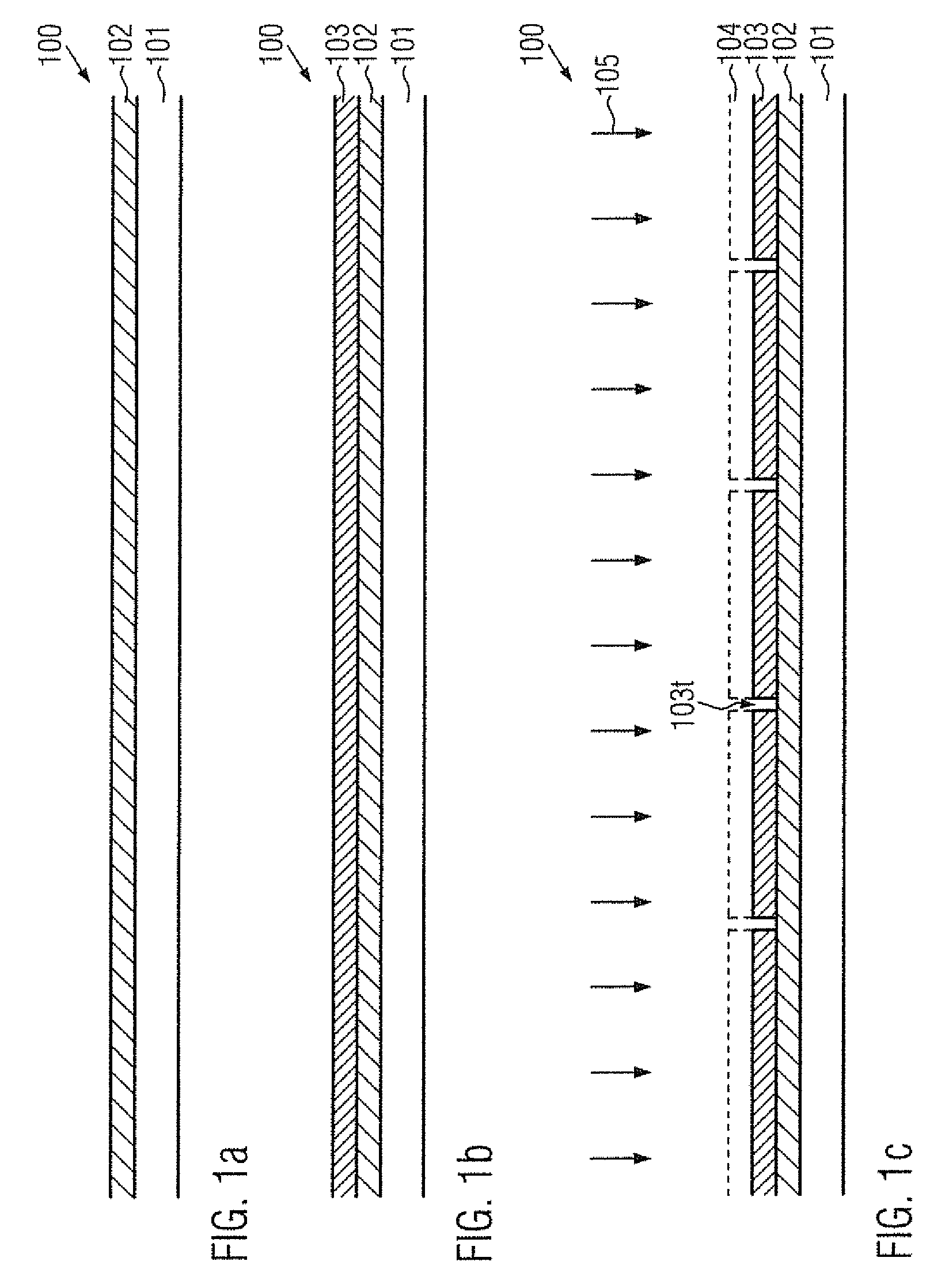
[0042]FIG. 1a schematically illustrates a cross-sectional view of a solar module 100 in a manufacturing stage, in which a carrier material 101, such as a semiconductor wafer and the like, is provided in order to receive a substrate material 102 of the solar module 100. The substrate material 102 may be selected as any appropriate carrier material, wherein in preferred embodiments substrate materials may be used, which may typically not be considered appropriate for applying conventional patterning techniques on the basis of laser scribing techniques. For example, the substrate material 102 may be generally a flexible material in the form of polyimide or any other plastic material.

[0043]It should be appreciated, however, that, although flexible substrates provide for superior performance in particular in indoor applications, basically the present invention may also be implemented in the context of any other carrier material, as are also typically used in conventional solar modules. T...


PUM


Abstract

Solar thin film modules are provided with reduced lateral dimensions of isolation trenches and contact trenches, which provide for a series connection of the individual solar cells. To this end lithography and etch techniques are applied to pattern the individual material layers, thereby reducing parasitic shunt leakages compared to conventional laser scribing techniques. In particular, there may be series connected solar cells formed on a flexible substrate material that are highly efficient in indoor applications.

Description

FIELD OF THE INVENTION[0001]Generally speaking, the present invention relates to solar cell technology, and in particular to solar cells for indoor applications.BACKGROUND OF THE INVENTION[0002]Thin-film solar cell technology based on appropriate semiconductive materials, such as amorphous silicon (a-Si:H), is very promising for generating low-cost solar energy. This thin-film solar cell technology may be used for cost-effective applications such as large area photovoltaic modules and cells applied to any appropriate carrier material. For example, semiconductor materials and metallization layers may be applied to flexible substrates, thereby enabling the production of lightweight rollable and / or foldable solar modules which allow efficient storage and transport.[0003]Generally, the particular size, shape and design of thin-film solar cells formed on flexible substrates allow for innovative design of circuit interconnections including efficient designs that may minimize the impact of...

Claims


Application Information

Patent Timeline
Patent Type & Authority Applications(United States)
IPC IPC(8): H01L31/05H01L31/18
CPCH01L31/0463Y02E10/50Y02E10/547Y02E10/548H01L31/022491H01L31/0312H01L31/03762H01L31/03926H01L31/0465H01L31/068H01L31/075
Inventor FOTI, MARINASPARTA, NOEMI GRAZIANALOMBARDO, SALVATOREDIMARCO, SILVESTRARAVESI, SEBASTIANOGERARDI, COSIMO
Owner STMICROELECTRONICS SRL
Why Eureka
Try Eureka