
Anorectal surgical instrument and anal dilator

a surgical instrument and anal dilator technology, applied in the field of medical instruments, can solve the problems of inconvenient use inability to visually determine whether other tissues are affected, and even unsafe, and achieve the effects of improving the success rate of surgical operations, facilitating operation and control, and avoiding negative influence on the application effect of existing anal dilators

Inactive Publication Date: 2013-02-07
B J ZH F PANTHER MEDICAL EQUIP
View PDF5 Cites 154 Cited by
  • Summary
  • Abstract
  • Description
  • Claims
  • Application Information

AI Technical Summary

Benefits of technology

This patent text describes an improved anal dilator that is made of transparent materials and has a luminescent light source. This allows surgeons to have a clear view of the entire operative field, especially the deep visual field, which makes the surgical operation safer and more convenient. The light source is external to the cylindrical body of the dilator, making it easy to operate and control without affecting the functionality of the dilator. Additionally, the hemorrhoid stapler has a transparent staple cartridge that allows for accurate and complete excision range, ultimately increasing the success rate of the surgical operation.

Problems solved by technology

However, the vascular cushion may become pathologic hypertrophy due to diarrhea, constipation, increased intra-abdominal pressure and so on, and then move down, thereby resulting in the hemorrhoid.
During the surgical operation, the visual field at the anus is not good, it is inconvenient, even unsafe, to use the existing anal dilator.
Since the space is small and the visual field is unclear, it is hard to perform the purse-string suture, hard to check whether a cut tissue has entirely entered the staple cartridge of the hemorrhoid stapler, and is impossible to visually determine whether other tissues, for example, the vagina of the female or a muscle layer of the intestinal canal, has entered into the opening of the stapler.
Once the surgeon makes a mistaken determination, it will lead to severe complication, for example, massive hemorrhage, anal vaginal fistula, postoperative stenosis and so on.

Method used


Image

  • Anorectal surgical instrument and anal dilator
  • Anorectal surgical instrument and anal dilator
  • Anorectal surgical instrument and anal dilator

Examples


first embodiment

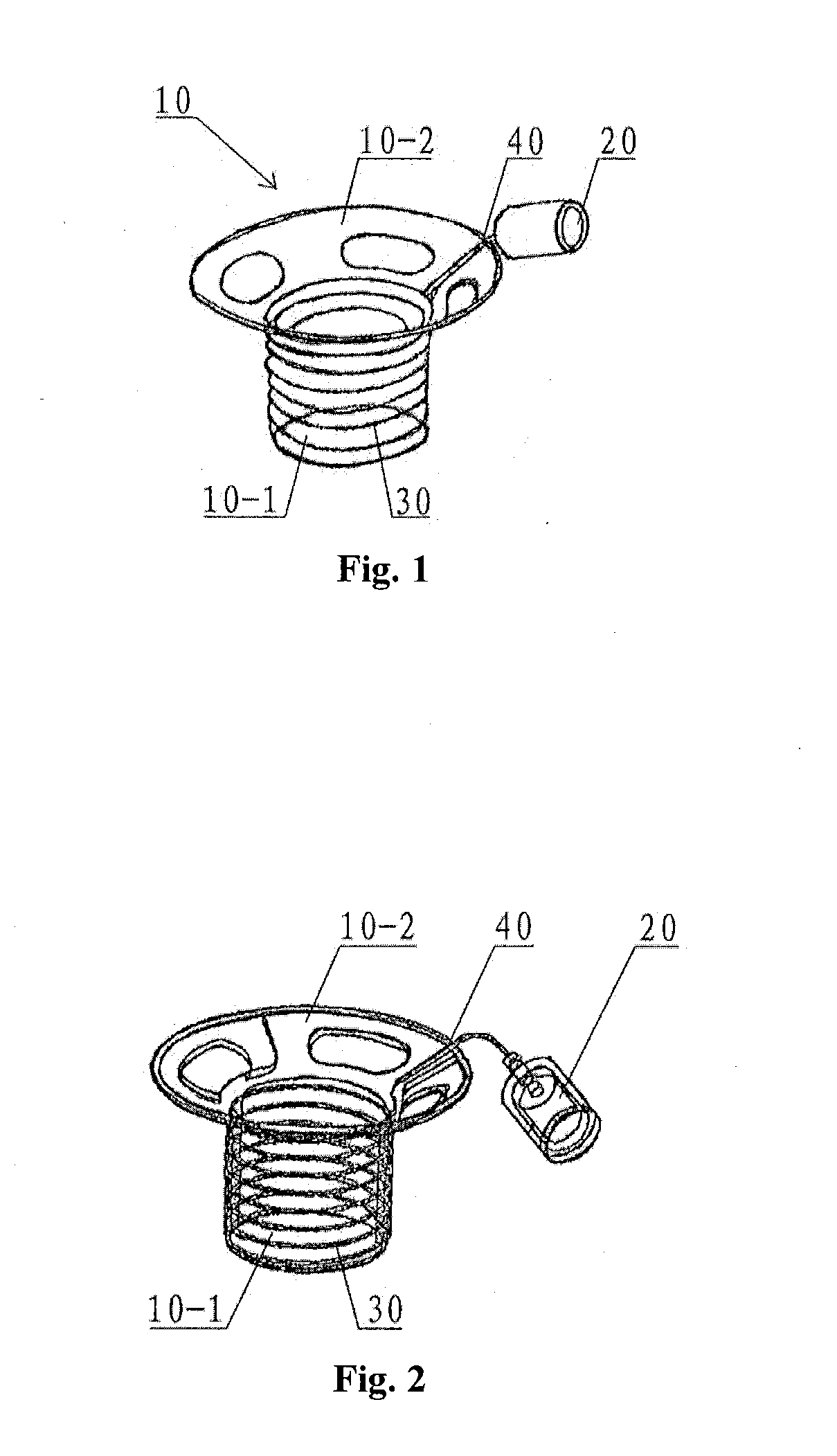
[0040]Referring to FIGS. 1 and 2, FIG. 1 is an outline view of an anal dilator according to the present application, and FIG. 2 is a structural view of the anal dilator shown in FIG. 1.

[0041]In the first embodiment, the anal dilator 10 according to the present application includes a transparent cylindrical body 10-1, with the cylindrical body 10-1 being provided on its top portion with an elastic enlarged edge 10-2. An outer contour of the whole anal dilator 10 is of an inverted hat shape, with the cylindrical body 10-1 corresponding to a hat body and the trumpet-shaped enlarged edge 10-2 corresponding to a hat edge. The cylindrical body 10-1 is marked with legible scales to facilitate observation and surgical operation of the surgeon. The trumpet-shaped enlarged edge 10-2 is uniformly provided with several hollow-out portions. A light source assembly 20 is arranged outside the enlarged edge 10-2. An optical fiber 30 is wound circumferentially around an outer wall of the cylindrical...

second embodiment

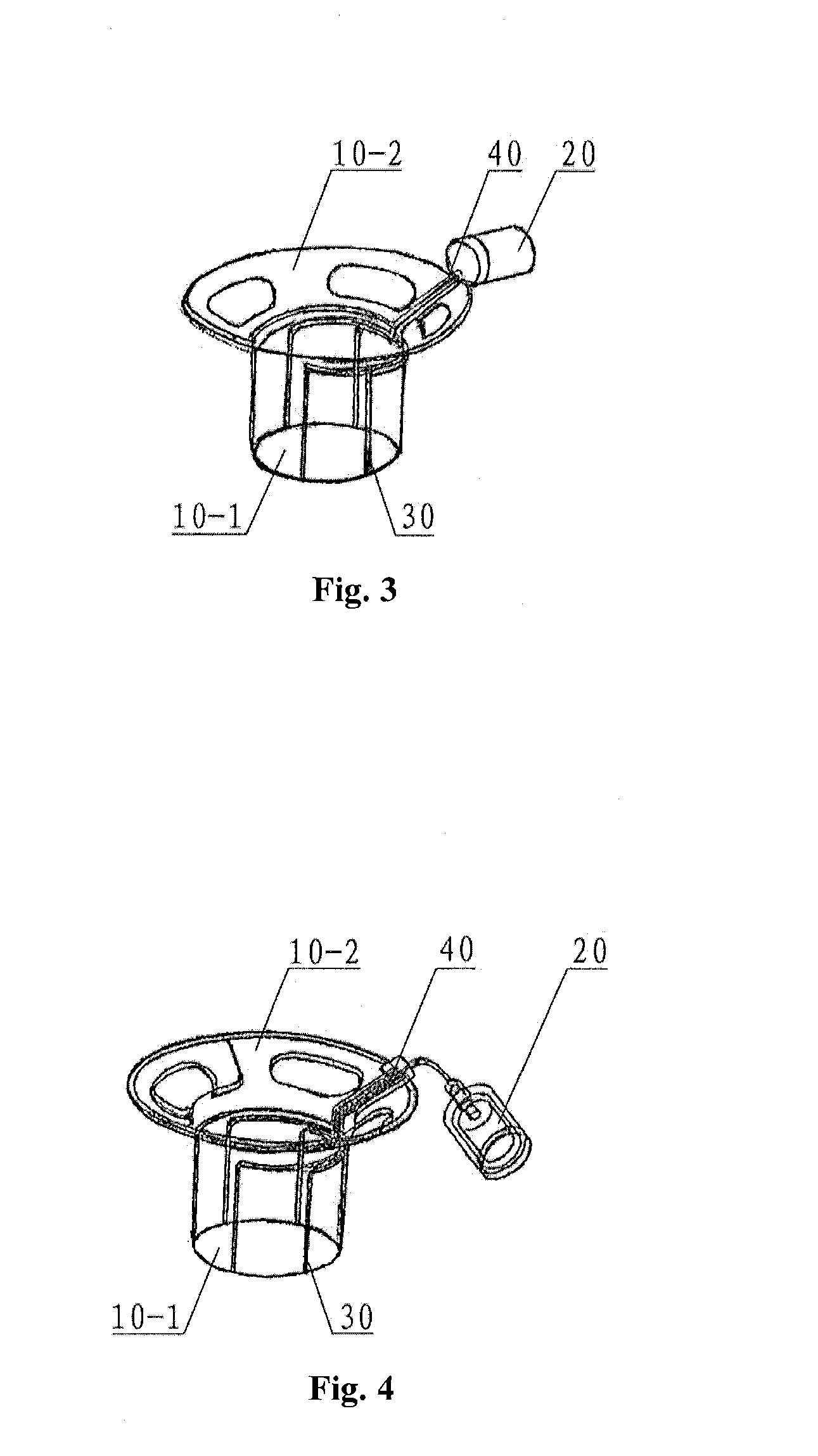
[0043]Referring to FIGS. 3 and 4, FIG. 3 is an outline view of the anal dilator according to the present application, and FIG. 4 is a structural view of the anal dilator shown in FIG. 3.

[0044]In the second embodiment, the anal dilator 10 according to the present application includes a transparent cylindrical body 10-1, with the cylindrical body 10-1 being provided on its top portion with an elastic enlarged edge 10-2. An outer contour of the whole anal dilator 10 is of an inverted hat shape, with the cylindrical body 10-1 corresponding to a hat body and the trumpet-shaped enlarged edge 10-2 corresponding to a hat edge. The cylindrical body 10-1 is marked with legible scales to facilitate observation and surgical operation of the surgeon. The trumpet-shaped enlarged edge 10-2 is made of medical rubber material and is uniformly provided with several hollow-out portions. A light source assembly 20 is arranged outside the enlarged edge 10-2. An optical fiber 30 is arranged, in a longitu...

third embodiment

[0048]Referring to FIGS. 5 to 9, FIG. 5 is an outline view of the anal dilator according to the present application, FIG. 6 is a structural schematic view of an external light source assembly shown in FIG. 5, FIG. 7 is a sectional view of the cylindrical body shown in FIG. 5, FIG. 8 is a partial enlarged schematic view of part I in FIG. 7, and FIG. 9 is a structural schematic view of the anal dilator shown in FIG. 5, with the external light source assembly being removed.

[0049]In the third embodiment, the anal dilator according to the present application includes a transparent cylindrical body 100, with the cylindrical body 100 being provided on its top portion with an elastic enlarged edge 200. The enlarged edge 200 is provided with two lateral wings, one of which is provided with a wedge-shaped hole 201. The cylindrical body 100 and the enlarged edge 200 are both made of transparent materials, and are formed into a double-layer structure inside which a gap is formed. The gap inside...


PUM

PropertyMeasurementUnit
widthaaaaaaaaaa
diameteraaaaaaaaaa
diameteraaaaaaaaaa

Abstract

An anal dilator (10) and an anorectal surgical instrument including the anal dilator (10). The anal dilator (10) includes a cylindrical body (10-1, 100) and an external light source assembly (20, 300) for illuminating surgical fields. The top of the body (10-1, 100) is an elastic enlarged edge (10-2, 200) and the external light source assembly (20, 300) is connected with the enlarged edge (10-2, 200). The anal dilator (10) is made of transparent materials. The surgical fields can be completely illuminated via a light path (101) by the light source during the surgery.

Description

[0001]This application is the national phase of International Application No. PCT / CN2010 / 078058, titled “ANORECTAL SURGICAL INSTRUMENT AND ANAL DILATOR”, filed on Oct. 25, 2010, which claims the benefits of priorities to Chinese patent application No. 200920220138.7 titled “DISPOSABLE HEMORRHOID ANASTOMAT WITH TRANSPARENT NAIL BIN” and Chinese patent application No. 200920220139.1 titled “ANAL DILATOR WITH COLD LIGHT SOURCE”, which are both filed with the Chinese State Intellectual Property Office on Oct. 26, 2009, and to Chinese patent application No. 201020570951.X titled “ANORECTAL SURGICAL INSTRUMENT AND ANAL DILATOR”, filed with the Chinese State Intellectual Property Office on Oct. 21, 2010. The entire disclosures thereof are incorporated herein by reference.FIELD OF THE INVENTION[0002]The present application relates to the technical field of medical instruments, in particular, to a surgical instrument used in surgical operations for treating anorectal diseases. The present ap...

Claims


Application Information

Patent Timeline
Patent Type & Authority Applications(United States)
IPC IPC(8): A61B1/06A61B17/115A61M29/02
CPCA61B1/0669A61B1/31A61B1/32A61M2210/1067A61B19/5202A61B2017/00902A61M29/00A61B17/0293A61B90/30
Inventor LI, XUEJUNLIU, QING
Owner B J ZH F PANTHER MEDICAL EQUIP
Learn More