Inline measuring apparatus and method

a technology of measuring apparatus and measuring method, which is applied in the direction of measuring device, material analysis using microwave means, instruments, etc., can solve the problems of reduced production, reduced chemical cost, and economic losses of petroleum industries

Active Publication Date: 2013-02-07
NORCE INNOVATION AS
View PDF6 Cites 37 Cited by
  • Summary
  • Abstract
  • Description
  • Claims
  • Application Information

AI Technical Summary

Benefits of technology

[0057]FIG. 6 is a graph of effective relative permittivity of a co-planar waveguide terminated by a hydrate layer backed by gas; there are several curves illustrating an effect on measurement of changing a spacing width w of the waveguide;

Problems solved by technology

Problems related to crystallization and / or deposition of wax, hydrate and scale during production and transportation of hydrocarbons are potentially capable of causing considerable economic losses to petroleum industries.
Moreover, break-through of formation water can also create problems.
These losses arise through the cost of chemicals, reduced production, equipment failure, and so on.
Flow assurance is thus becoming an increasing challenge as depth and step-out distances to new oil and gas fields are increasing in order to exploit more marginal fossil fuel reserves.
Hydrates exhibit complex behaviour which represents a problem, given a large number of micro- and macro-scale phenomena involved in the process of hydrate formation, such as nucleation, crystal growth, agglomeration, break-up, entrainment and deposition along pipelines in transient multiphase flow conditions.
In many cases, high safety margins are used to account for uncertainties associated with measuring the above factors, as limited localized monitoring solutions are available along the pipeline; in other words, measurements indicative of, for example, hydrate formation are only available at periodic spatial intervals along the pipeline.
This results in a high consumption of an inhibitor liquid, frequent pigging to avoid blocking of pipelines, in addition to the environmental challenges associated with such operations.
Due to a high inhibitor dosage requirement, a significant increase in capital expenditure and operational expenditure can arise, in particular at high water cut conditions.
Also, despite all these efforts, hydrates do form that can have considerable economic and safety impacts.
Moreover, early detection of one or more break-throughs of formation water is also important in industry, on account of production of formation water potentially resulting in sudden increases in water cut and thereby increased risk of hydrate formation arising.
This method is based on bulk measurements, and is not applicable to detecting very thin hydrate coatings at an inner wall of a pipe.
However, such a sensor topology applies a point measurement, namely it is only sensitive to fluid properties in a small spatial region around the probe.
This spatially localized sensitivity is a drawback, on account of a single point measurement giving a measurement volume which is so limited such that it may not be representative for an actual hydrate deposition.
However, such an approach would be costly to implement on account of each of these sensors requiring a separate corresponding electronics unit in order to measure at all points simultaneously.
Moreover, the measurement precision of an open-ended coaxial probe is limited, and cannot be controlled independently of the probe's sensitivity depth and frequency operation range.
This method is applicable for identifying gas hydrate nucleation, but it is however not suitable for detecting thin hydrate coatings.
However, these acoustic methods do not provide a required sensitivity for detecting very thin layers of coating for the case of non-uniform layers with varying bonding between pipe and layer; thus, detection of thin non-uniform coatings associated with hydrate formation is not possible using acoustic methods for providing warnings.
Moreover, a depth sensitivity of apparatus and associated measurement techniques in these patents is difficult to control, thereby potentially resulting in unreliable measurements being achieved in practice.

Method used


Image

  • Inline measuring apparatus and method
  • Inline measuring apparatus and method
  • Inline measuring apparatus and method

Examples


Embodiment Construction

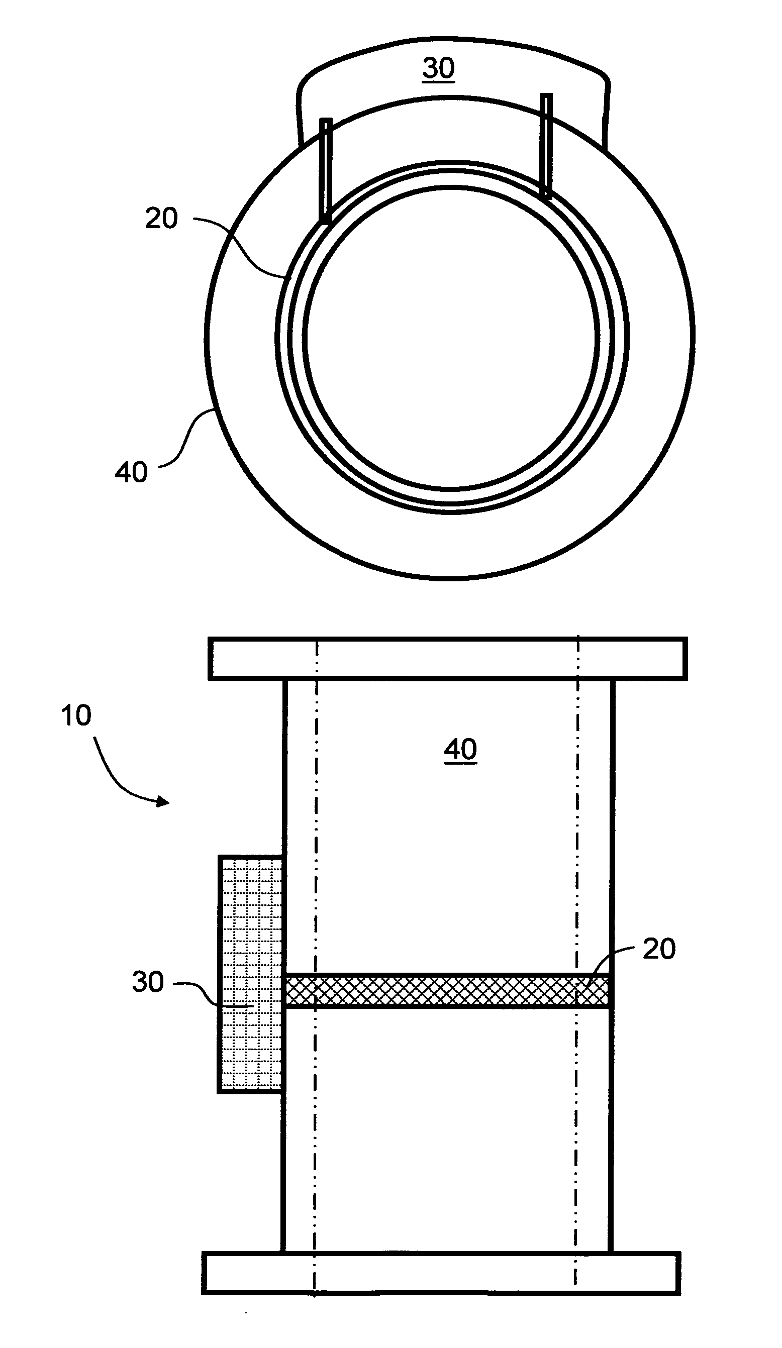
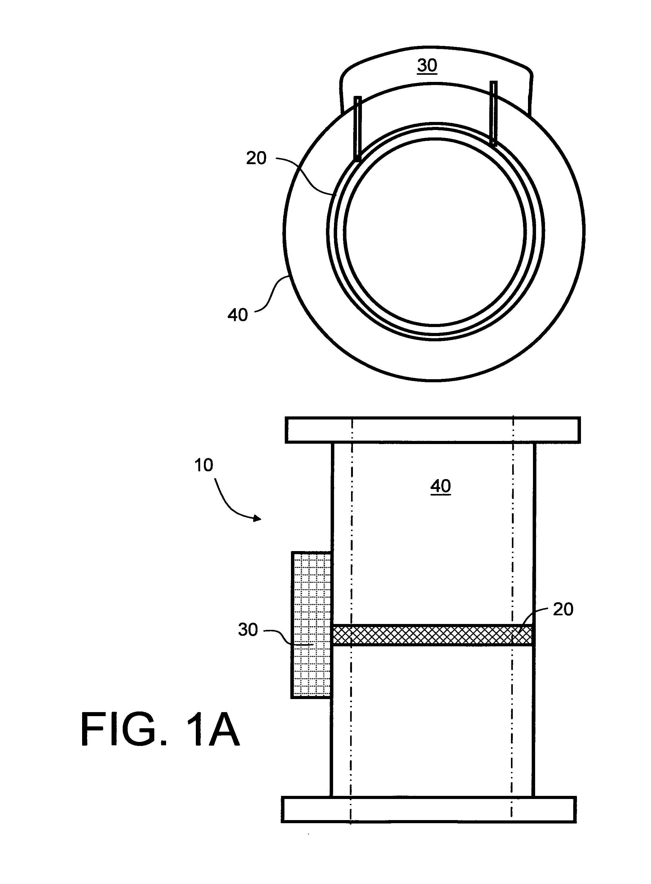
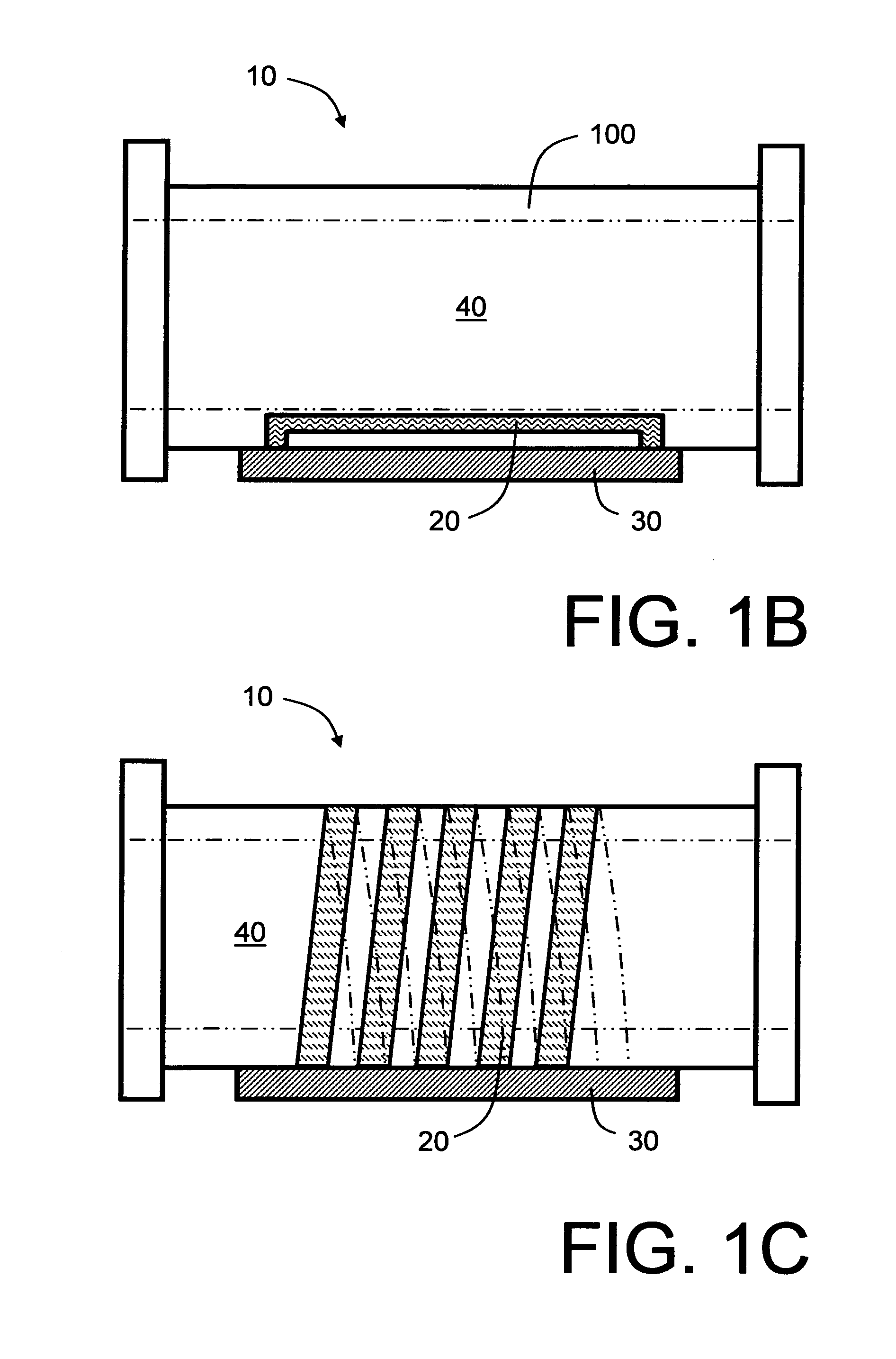
[0061]In overview, the present invention concerns apparatus which utilize complex permittivity measurements within a measurement volume spatially close to a wall of a pipe to detect thin layers of hydrate, scale, and / or wax deposits, and / or amounts of formation water in a liquid film close to a pipe wall. Equipment based on complex permittivity measurements are in use in other fields, for example as described in:[0062](i) US patent application no. 2009 / 152624 which pertains to use of a coplanar waveguide for non-invasive measurement on living tissue; and[0063](ii) U.S. Pat. No. 5,223,796 which pertains to measuring dielectric properties of a material,

but their application to detecting hydrate, wax, break-through of formation water and / or scale deposition is not known.

[0064]The present invention relates, for example, to a method and apparatus for measuring deposits of gas hydrates on an inside region of a pipe, and is applicable, for example, for providing early warning of hydrate fo...


PUM

PropertyMeasurementUnit
thicknessaaaaaaaaaa
frequencyaaaaaaaaaa
frequencyaaaaaaaaaa

Abstract

An inline measuring apparatus (10) is operable to measure hydrate, wax, break-through of formation water and/or scale (150) on an inside surface of a wall (100) of a pipe (40) for guiding fluid. The apparatus (10) includes an electronics unit (30) coupled to a sensor arrangement (20) disposed in a spatial extensive manner into the wall (100) of the pipe (40) for sensing the growth (150). The electronics unit (30) in cooperation with the sensor arrangement (20) Is operable to perform a series of dielectric measurements at a plurality of interrogating frequencies for determining a nature and spatial extent of the growth (150). The sensor arrangement (20) includes a plurality of sensors have mutually different sensing characteristics in relation to their spatial sensing region and/or their sensitivity to different fluid components present in operation within the pipe (40). Optionally, the apparatus (10) is capable of being operated synergistically in a plurality of different operating modes which enables detection of thin film formation at an inside wall of the pipe (40) as well as a measurement of bulk properties of fluid present within the pipe (40).

Description

FIELD OF THE INVENTION[0001]The present invention relates to inline measuring apparatus for detecting hydrate formation and for assuring flow, for example to apparatus for sensing hydrate formation within pipes, namely close to walls of the pipes, which could potentially obstruct flow. Moreover, the present invention concerns methods of detecting hydrate formation and assuring flow. Furthermore, the present invention also concerns software recorded on data storage media, wherein the software is executable on computing hardware for use when implementing these methods. Additionally, the invention relates to apparatus and associated methods of detecting growth of wax and / or scale and / or break-through of formation water.BACKGROUND OF THE INVENTION[0002]Problems related to crystallization and / or deposition of wax, hydrate and scale during production and transportation of hydrocarbons are potentially capable of causing considerable economic losses to petroleum industries. Moreover, break-...

Claims


Application Information

Patent Timeline
Patent Type & Authority Applications(United States)
IPC IPC(8): G01N22/00
CPCG01N33/28G01N22/00
Inventor FOLGEROE, KJETILKOCBACH, JAN
Owner NORCE INNOVATION AS
Why Eureka
Try Eureka