Control of a machining operation

a technology of control and operation, applied in the direction of program-controlled manipulators, total factory control, programme control, etc., can solve problems such as compromising the accuracy of determination, and achieve the effect of improving the accuracy of the known position of the robotic manipulator

Inactive Publication Date: 2013-02-07
ROLLS ROYCE PLC
View PDF5 Cites 13 Cited by
  • Summary
  • Abstract
  • Description
  • Claims
  • Application Information

AI Technical Summary

Benefits of technology

[0017]using the determined errors in step (v) to improve the accuracy of the known position of the robotic manipulator at the machining station.

Problems solved by technology

In machining processes which use robotic handling to determine the component position, the accuracy of the determination can be compromised by inaccuracy in the robot's position (caused, for example, by backlash).

Method used


Image

  • Control of a machining operation
  • Control of a machining operation
  • Control of a machining operation

Examples


Embodiment Construction

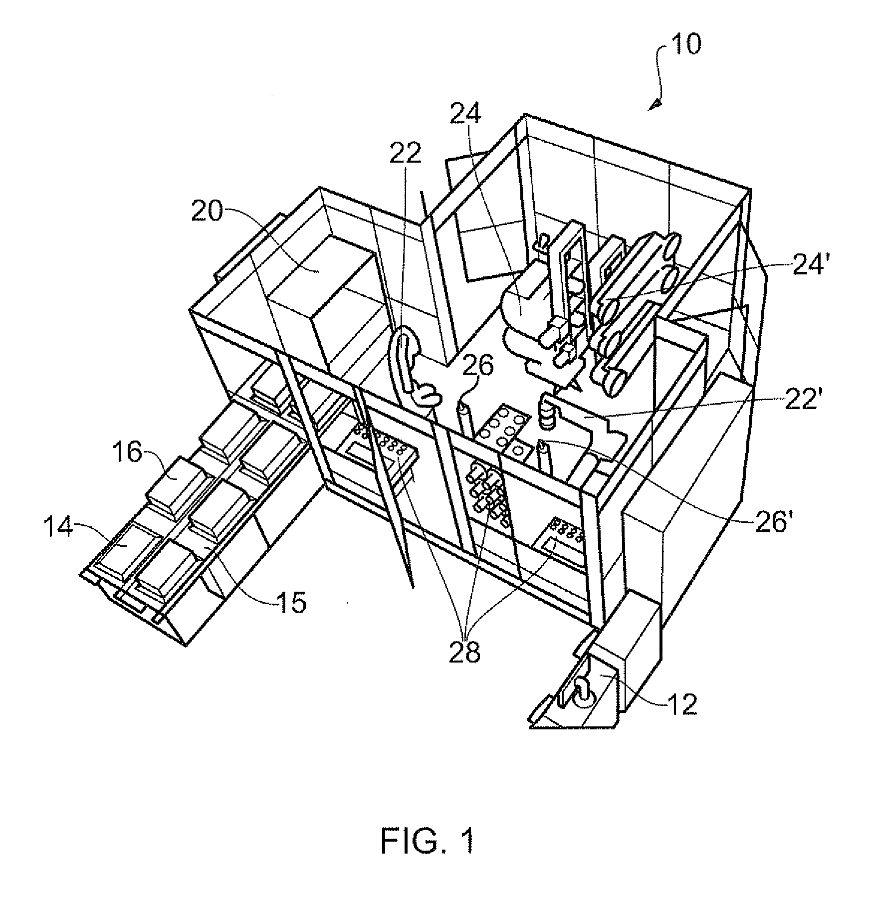
[0043]In FIG. 1, a machining cell is shown generally at 10. The cell 10 includes a number of machines and devices, whose purpose and operation will be explained below. These machines and devices are linked to a computer 12 which can store and process information received from the machines and devices, or their controllers, and issue instructions to them.

[0044]This cell is equipped to perform machining operations, such as grinding and polishing, on a rotor blade of a gas turbine engine. The cell can be used to perform single- or multiple-stage manufacturing operations.

[0045]Incoming blades are brought into the cell on an input conveyor 14. Part holders 16 are queued on the conveyor, the holders containing, for example, blades on which a machining operation is to be performed.

[0046]An inspection device 20, containing e.g. an optical reader, can detect the positions of the blades within the part holder 16 at the front of the queue, and can also read a component identifier, such as a ba...


PUM


Abstract

A method for controlling the machining of a component includes the steps of: (i) measuring predetermined dimensions of a component; (ii) comparing the measured dimensions against design data defining a required shape for the component; (iii) using the results of the comparison to define material removal that is needed to bring the component to the required shape; (iv) delivering the component to a site at or adjacent to a machining station having a material removal tool, the component being gripped by a robotic manipulator at said site; (v) using the defined material removal and the known position of the robotic manipulator at the machining station to determine movements of the material removal tool that will produce the required shape for the component; and (vi) performing a machining operation on the component at the machining station using the determined movements while maintaining the grip on the component by the robotic manipulator.

Description

FIELD OF THE INVENTION[0001]The present invention relates to the machining of components, and more particularly to methods for controlling the machines used to perform such operations. In an example of the invention, it is applied to the profile forming of a rotor blade aerofoil for a gas turbine engine.BACKGROUND OF THE INVENTION[0002]In a gas turbine engine, each of the rotor blades and stator vanes is of aerofoil cross-section shape and must conform with its intended design, within certain specification limits. For example, each aerofoil has a leading edge designed with a complex geometry to deliver a specific effect. Deviations from the optimum design may result in undesirable reductions in performance, such as aerodynamic stall, compressor surge or reduction in engine efficiency. In some circumstances, relatively small deviations may have significant effects on performance. A similar but different complex geometry governs the definition of the trailing edge of an aerofoil.[0003...

Claims


Application Information

Patent Timeline
Patent Type & Authority Applications(United States)
IPC IPC(8): G06F19/18
CPCB25J9/1692G05B19/41815G05B2219/45147G05B2219/40071G05B2219/39056Y02P90/02
Inventor CAMERON, MITCHEL
Owner ROLLS ROYCE PLC
Why Eureka
Try Eureka