
Multiple hydraulic circuit pressure sensor

Inactive Publication Date: 2013-02-14
DELPHI TECH INC
View PDF2 Cites 0 Cited by
  • Summary
  • Abstract
  • Description
  • Claims
  • Application Information

AI Technical Summary

Benefits of technology

The present invention offers a cost-effective and compact method to directly measure the pressure of hydraulic control systems in complex automotive systems. This enables real-time pressure information to be shared with the associated controller, which can then perform dynamic pressure control algorithms within the transmission. This approach enables easier and more precise calibration of the transmission, better compensation for wear and fluid contamination, and reduction of parasitic losses, resulting in improved vehicle fuel economy and lower emissions.

Problems solved by technology

Known transmission control technology utilizes solenoid “current” sensing to close the control loop within the transmission requiring extremely high precision, costly transmission components to achieve the desired functionality.
In addition to being expensive, known sensors are large and can be difficult to package in a confined automotive environment.
As a result, closed loop pressure control techniques have not been widely applied to automotive applications.

Method used


Image

  • Multiple hydraulic circuit pressure sensor
  • Multiple hydraulic circuit pressure sensor
  • Multiple hydraulic circuit pressure sensor

Examples


Embodiment Construction

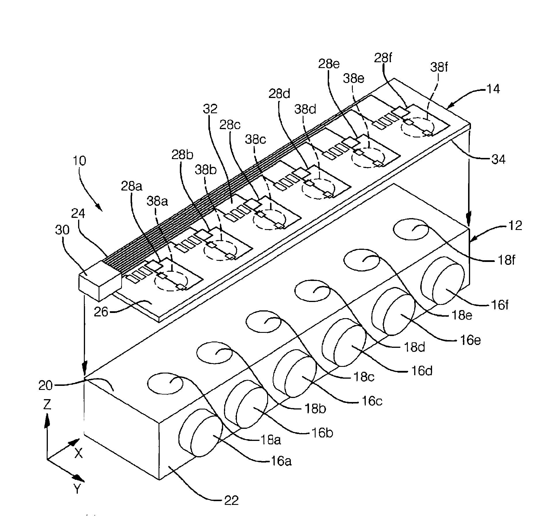
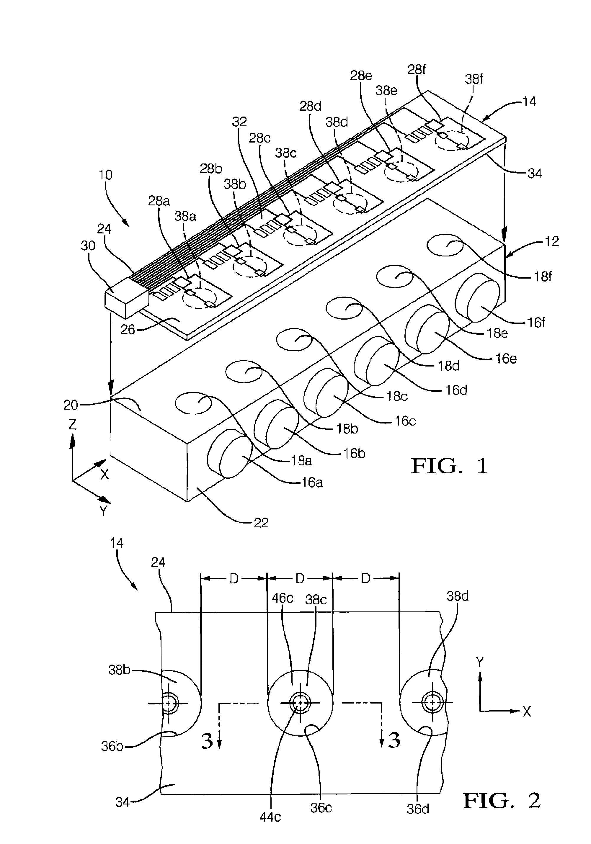
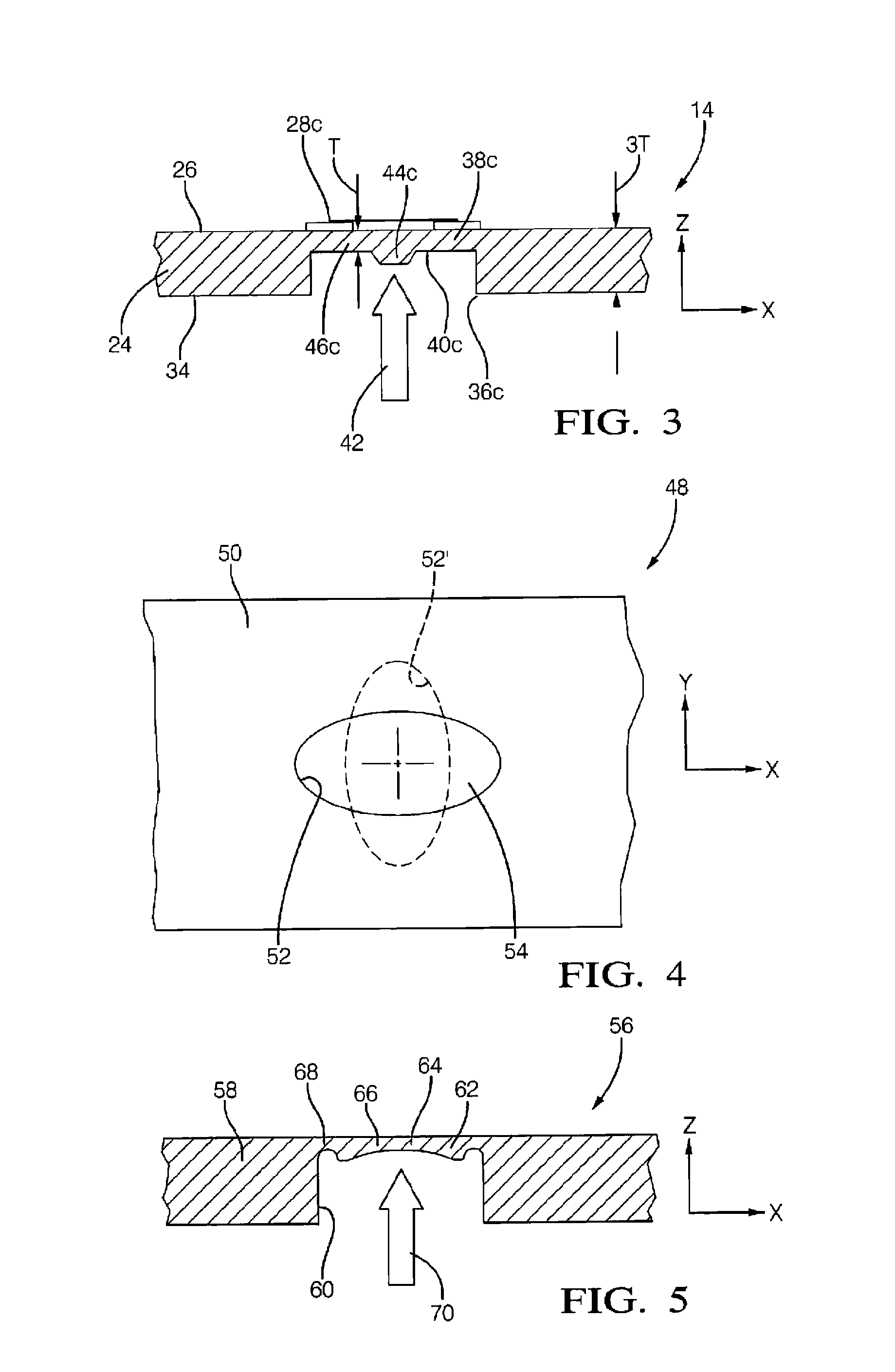
[0018]The present invention describes a multiple hydraulic circuit pressure sensor for automotive transmission applications. The sensor utilizes thick film electronics printing techniques on a stainless steel or aluminum plate to create a unified structure with multiple sensor locations that can be mounted over multiple solenoid pressure port locations inside the transmission. The plate contains Wheatstone bridge thick film printed resistor configurations over shaped diaphragm locations to measure diaphragm deformation due to applied pressure. In addition, the plate forms its own “circuit board” containing all of the circuit routing and reflow solder electrical components necessary to create a self-contained, functional multiple location sensing circuit. The plate construction is impervious to immersion in hot transmission fluid.

[0019]The sensing plate allows several independent sensing locations to be produced in one pass through the manufacturing value stream (e.g. multiple sensin...


PUM


Abstract

A hydraulic solenoid assembly for complex vehicle-borne control systems, such as automatic transmissions, includes a solenoid body or unitary housing operatively enclosing two or more solenoid valves. Each valve has a pressure port extending to an outer surface of the housing, emerging in a spaced-apart matrix. A metal (stainless steel or aluminum) sensor plate is mounted to the outer surface of the housing so as to sealingly overlay the pressure ports. A diaphragm is formed in the sensor plate for each solenoid valve and registers with its associated pressure port. Electrical components, such as thick file resistors arranged in a Wheatstone bridge network are printed or mounted to an outer surface of each diaphragm. The bridge networks are electrically connected to a control circuit and function to output signals as a function of hydraulic pressure induced displacement of the associated diaphragm.

Description

CROSS REFERENCE TO RELATED APPLICATIONS[0001]This application is a national stage application under 35 U.S.C. 371 of PCT Application No. PCT / US2011 / 038982 having an international filing date of 3 Jun. 2011, which designated the United States, which PCT application claimed the benefit of U.S. provisional patent application Ser. No. 61 / 351,376 filed 4 Jun. 2010, entitled “Multiple Hydraulic Circuit Pressure Sensor”, the entire disclosure of each of which are hereby incorporated herein by reference.TECHNICAL FIELD[0002]The present invention relates generally to hydraulic solenoid valves, and particularly to the control of complex hydraulic systems employing multiple solenoid valves using direct hydraulic circuit pressure sensing techniques.BACKGROUND OF THE INVENTION[0003]Known transmission control technology utilizes solenoid “current” sensing to close the control loop within the transmission requiring extremely high precision, costly transmission components to achieve the desired fun...

Claims


Application Information

Patent Timeline
IPC IPC(8): G01L9/04G01L9/02
CPCG01L15/00G01L9/0055
Inventor DAHLGREN, DANIEL R.LAWLYES, DANIEL A.NAEGELI, MARKUSISENBERG, JOHN K.LITTLE, LEWIS HENRY
Owner DELPHI TECH INC
Features
  • Generate Ideas
  • Intellectual Property
  • Life Sciences
  • Materials
  • Tech Scout
  • Unparalleled Data Quality
  • Higher Quality Content
  • 60% Fewer Hallucinations
Learn More