Piezoelectric fan and air cooling apparatus using the piezoelectric fan

a piezoelectric fan and air cooling technology, applied in lighting and heating apparatuses, piston pumps, semiconductor/solid-state device details, etc., can solve the problems of increasing the load on the piezoelectric element, affecting the operation of the portable electronic apparatus, and affecting the operation so as to reduce the displacement of the piezoelectric element, prevent and suppress the occurrence of fatigue failure, and reduce the distortion of processing.

Active Publication Date: 2013-02-14
MURATA MFG CO LTD
View PDF12 Cites 5 Cited by
  • Summary
  • Abstract
  • Description
  • Claims
  • Application Information

AI Technical Summary

Benefits of technology

[0016]The bent portion may include a round surface. Although the bent portion may include a square edge, fatigue failure due to process distortion is likely to occur. On the other hand, when a round surface is included in the bent portion, distortion in processing is alleviated and occurrence of fatigue failure is prevented and suppressed.
[0017]It is preferable to provide a structure in which an extension portion to which a piezoelectric element is not attached is provided at the one end of the vibration plate in the length direction, and the extension portion is supported in a fixed manner by a support member. Although the end portion of the piezoelectric element may be supported in a fixed manner, the support member prevents and suppresses the displacement of the piezoelectric element in that case and, hence, conversion efficiency from electric energy to vibration energy is decreased. On the other hand, when the extension portion of the vibration plate is supported in a fixed manner, it becomes easy to displace the piezoelectric element freely, whereby the conversion efficiency is increased.
[0018]It is preferable to provide a driver circuit that keeps the blades in a resonant state by sweeping a frequency of a signal supplied to the piezoelectric element over a predetermined range, automatically detecting a resonant frequency of the blades on the basis of a change in impedance in the sweeping, and driving the piezoelectric element at the resonant frequency. A known example of a driver circuit to drive the piezoelectric element excites the blades by applying a signal having a predetermined frequency. However, such a driver circuit cannot excite the blades efficiently when there is a difference between the frequency of the signal and the resonant frequency of the blades. Hence, a driver circuit may be used which keeps the blades in a resonant state by sweeping a frequency of a signal supplied to the piezoelectric element over a predetermined range, automatically detecting a resonant frequency of the blades, and driving the piezoelectric element at the resonant frequency. In this case, when variations in resonant frequency among individual blades are large as in the virtual example, the driver circuit may not operate normally since the driver circuit may detect a plurality of frequencies. In addition, a beat may be generated in the command signal of the driver circuit. In the piezoelectric fan of various preferred embodiments of the present invention, since the vibration plate preferably is bent at a position before a position where the vibration plate is divided into a plurality of blades, variations in resonant frequency among the blades are small, and the automatic-detection driver circuit can detect a proper frequency. Hence, the blades can be efficiently excited at an optimal frequency.
[0019]When the piezoelectric fan is applied to a heat sink having a plurality of heat dissipation fins arranged side by side with spaces therebetween, an air cooling apparatus can be realized. In other words, the plurality of the blades of the piezoelectric fan are inserted between the heat dissipation fins such that an excitation direction of the blades is parallel or substantially parallel with side surfaces of the heat dissipation fins. Thereby, air between the heat dissipation fins is efficiently exhausted and a small air cooling apparatus is realized since the amount of protrusion of the piezoelectric fan from the heat sink is reduced.
[0020]In the air cooling apparatus described above, it is preferable that the plurality of the blades of the piezoelectric fan be inserted in a direction perpendicular or substantially perpendicular to a bottom surface of the heat sink, and the piezoelectric element be arranged in parallel or substantially in parallel with top surfaces of the fins of the heat sink. In this case, the center of the bottom surface of the heat sink can be intensively cooled and the piezoelectric element can be arranged along the upper portion of the heat sink, resulting in space saving.
[0021]As has been described above, according to various preferred embodiments of the present invention, since a bent portion is formed at a position before a position at which a plurality of the blades have been formed, variations in resonant frequency among the blades can be reduced. Hence, the amplitudes of all the blades can be made to be approximately uniform, and uniform cooling effects are obtained. Further, since the cross-sectional area of the bent portion is increased, stress concentration in the bent portion is reduced, whereby reliability against fatigue failure in the bent portion is increased.

Problems solved by technology

In recent years, because of a reduction in size and increasing component mounting density, portable electronic apparatuses have a problem with exhausting heat that is generated within the electronic apparatuses.
As a result, the load on the piezoelectric element increases and, hence, reliability may decrease due to, for example, generation of cracks in the piezoelectric element.
As a result, an excitation effect with long-term stability is not realized.
In addition, since a structure is employed in which a single blade is attached to a single piezoelectric element, blades cannot be inserted between the plurality of fins of a heat sink and, hence, warm air between the fins cannot be efficiently exhausted.

Method used


Image

  • Piezoelectric fan and air cooling apparatus using the piezoelectric fan
  • Piezoelectric fan and air cooling apparatus using the piezoelectric fan
  • Piezoelectric fan and air cooling apparatus using the piezoelectric fan

Examples


Embodiment Construction

[0035]Hereinafter, preferred embodiments of the present invention are described with reference to the drawings.

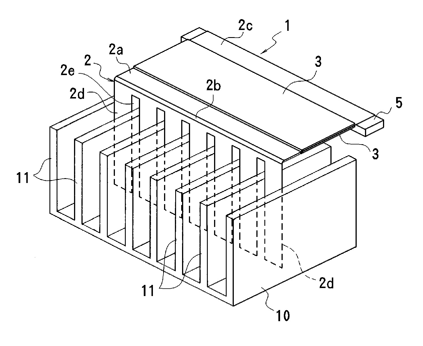
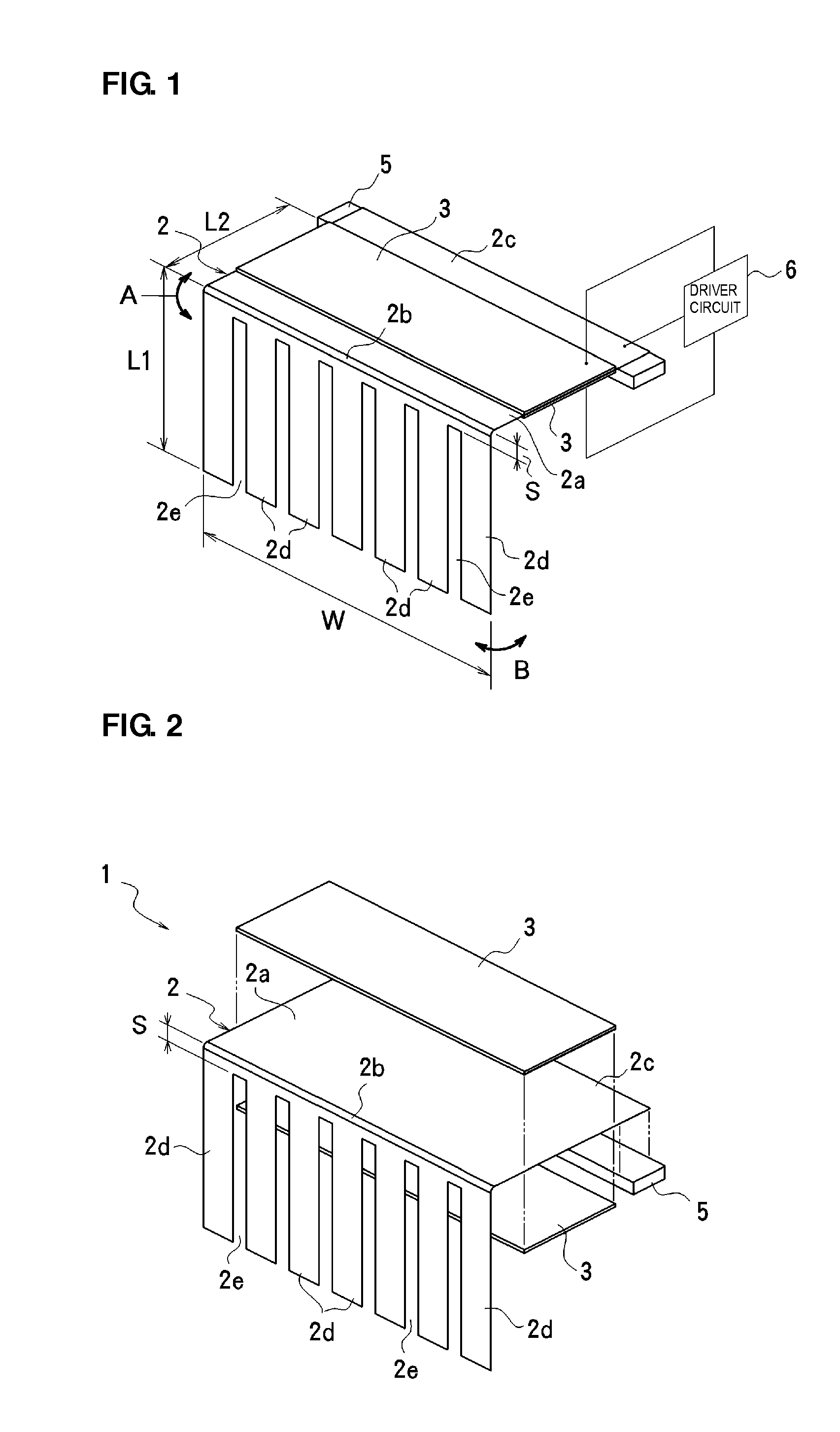
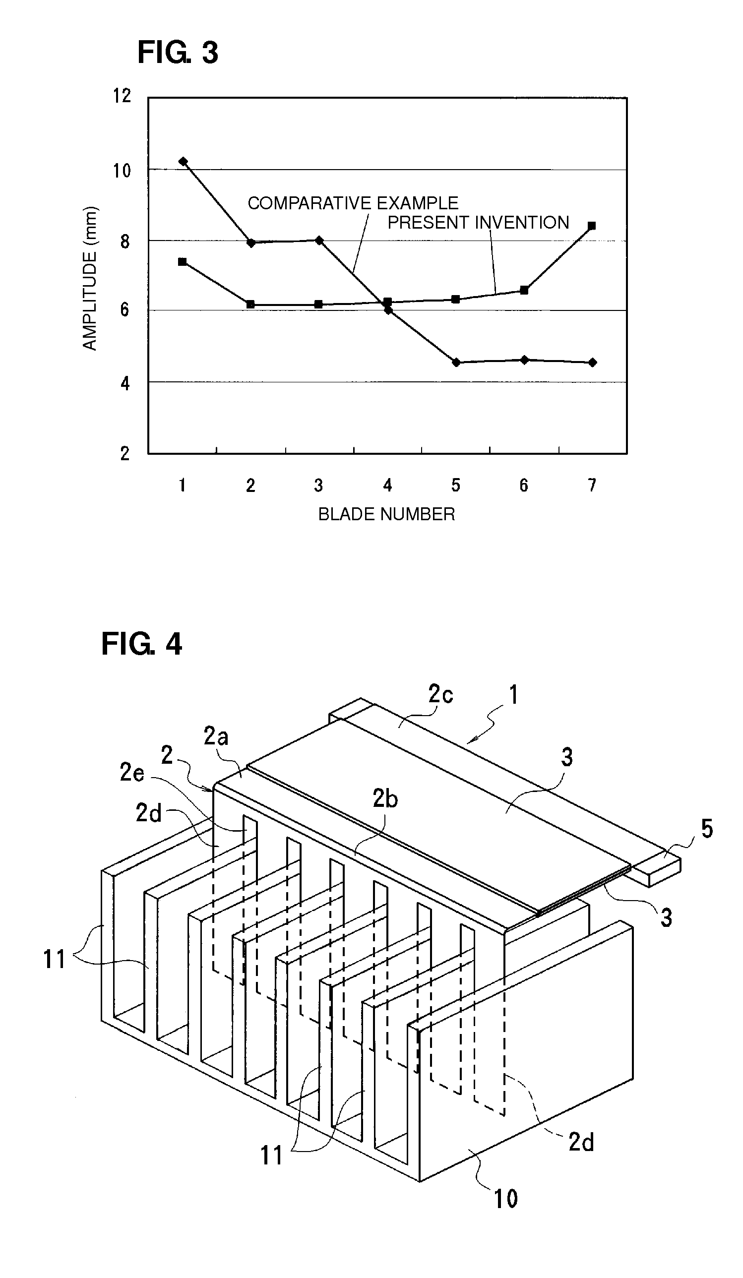
[0036]FIG. 1 and FIG. 2 illustrate a first preferred embodiment of a piezoelectric fan according to the present invention. This piezoelectric fan 1 includes a vibration plate 2 that preferably is a thin metal plate, such as a stainless plate, for example. A planar substrate portion 2a is provided on one end (fixed end) side of the vibration plate 2 in the length direction, and piezoelectric elements 3 and 3 are attached on the front and back surfaces of the substrate portion 2a, whereby a bimorph actuator is provided. Note that by attaching the piezoelectric element 3 on one surface of the substrate portion 2a, a unimorph actuator may be provided. The other end (free end) side of the vibration plate 2 in the length direction includes a plurality (for example, seven in this case) of blades 2d integrally provided thereon by forming a plurality of parallel slits 2e. A 90° bent...


PUM


Abstract

A piezoelectric fan includes a vibration plate one end of which in a length direction is supported in a fixed manner and the other end of which in the length direction is a free end; and piezoelectric elements, attached on at least one of front and back surfaces of the vibration plate. In an intermediate portion of the vibration plate in the length direction, a right-angle bent portion is provided, and a plurality of divided blades are defined by slits in an area of the vibration plate extending from the free end to a position located a predetermined distance from the bent portion toward the free end. The piezoelectric element is attached on the portion of the vibration plate between the fixed end and the bent portion. Hence, variations in resonant frequency among the blades are reduced and the blades are efficiently excited using a common piezoelectric element.

Description

BACKGROUND OF THE INVENTION[0001]1. Field of the Invention[0002]The present invention relates to piezoelectric fans and air cooling apparatuses that vibrate blades by driving piezoelectric elements, thereby exhausting warm air from a heat source such as a heat sink.[0003]2. Description of the Related Art[0004]In recent years, because of a reduction in size and increasing component mounting density, portable electronic apparatuses have a problem with exhausting heat that is generated within the electronic apparatuses. In order to efficiently cool such electronic apparatuses by air cooling, air cooling apparatuses called piezoelectric fans have been proposed.[0005]The following page of the Internet (PC watch): HTTP: / / pc.watch.impress.co.jp / docs / 2007 / 0423 / intel.htm proposes a piezoelectric fan that uses a piezoelectric element. In this piezoelectric fan, as illustrated in FIG. 5, piezoelectric elements 22 are pasted on both surfaces of a planar metal plate 21 at one end, thereby formin...

Claims


Application Information

Patent Timeline
Patent Type & Authority Applications(United States)
IPC IPC(8): F28F13/12F04D33/00F04D27/00F04D25/06
CPCF04D33/00H01L23/467H01L2924/3011H05K7/20172H01L2924/0002H01L2924/00
Inventor TANIDA, MASAYOSHISUNAGA, MIDORIWADA, HIROAKI
Owner MURATA MFG CO LTD
Why Eureka
Try Eureka