

Highly reactive fluid fan coupling device
- Summary
- Abstract
- Description
- Claims
- Application Information
AI Technical Summary
Benefits of technology
Problems solved by technology
Method used
Image

Examples
example 1
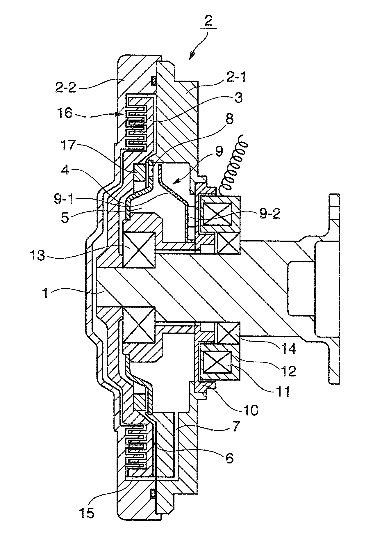
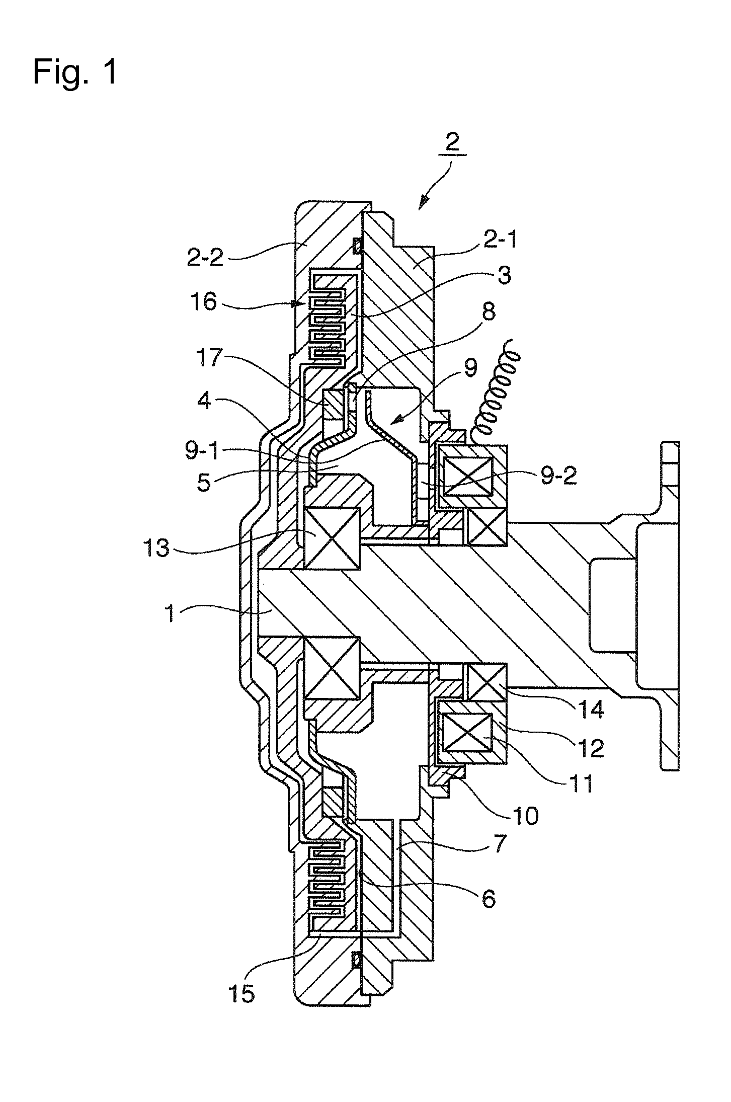
[0034]The externally-controlled fluid-type fan coupling device shown in FIG. 1 was used, and the reaction rates up to torque transmission at a time of normal OFF rotation (500 rpm) by excitation of the electromagnet and from a state where control to OFF rotation(150 rpm) has been made assuming the problem in the snowplow vehicle by excitation of the electromagnet were adopted as test conditions, and the test results are shown in FIG. 6 (OFF rotation: 500 rpm) and FIG. 7 (OFF rotation: 150 rpm) while being compared with a conventional example (without the ring).
[0035]Ring adopted (separate member)
[0036]A ring having a flat face formed with radial grooves therein shown in FIG. 4B (hereinafter, called “radially-grooved ring”)[0037]Clearance (gap) between the ring and the partition plate[0038]0.3 mm[0039]Viscosity of oil[0040]12,500 cst
[0041]As is clear from the results shown in FIGS. 6 and 7, in the test of the normal OFF rotation (500 rpm), while the fan coupling device having the rin...
example 2
[0042]The same externally-controlled fluid-type fan coupling device as in Example 1 was used, the respective effects of the following four types of rings of the present invention under the same test conditions as in Example 1 were compared with each other, and the results of comparison are shown in FIG. 8 (OFF rotation: 500 rpm) and FIG. 9 (OFF rotation: 150 rpm).
[0043]Rings employed (separate members) p The four types of rings shown in FIGS. 4A to 4D: FIG. 4A showing a ring having a plain flat face (hereinafter, called “plain ring”); FIG. 4B showing a ring having a flat face formed with radial grooves therein (hereinafter, called “radially-grooved ring”); FIG. 4C showing a ring having a flat face formed with radial protrusions thereon (hereinafter, called “radially-protruded ring”); and FIG. 4D showing a ring having a flat face formed with a labyrinthine groove 21 therein (hereinafter called “labyrinthine ring”).[0044]Clearance (gap) between the ring and the partition plate[0045]0....
example 3
[0049]The radially-grooved ring (B) was installed in the same externally-controlled fluid-type fan coupling device as in Example 1, the reaction rates of the fan coupling devices with different clearances (gaps) between the ring and the partition plate under the same test conditions were compared, and the results of comparison are shown in FIG. 10 (OFF rotation: 500 rpm) and FIG. 11 (OFF rotation: 150 rpm).
[0050]Ring adopted (separate member)
[0051]The radially-grooved ring shown in FIG. 4B[0052]Clearance (gap) between the ring and the partition plate[0053]0.3 to 1.0 mm[0054]Viscosity of oil[0055]12,500 cst
[0056]As is clear from the results shown in FIGS. 10 and 11, in the test of the normal OFF rotation (500 rpm), as shown in FIG. 10, the respective fan coupling devices with 0.3 mm, 0.5 mm, 0.7 mm, and 1.0 mm of clearances quickly reacted within over 10 seconds after a control signal was turned on, and, among them, the respective fan coupling devices with 0.3 mm, 0.5 mm, and 0.7 mm ...
PUM
 Abstract
Description
Claims
Application Information