
Control method of hybrid vehicle

Inactive Publication Date: 2013-02-14
HYUNDAI MOTOR CO LTD
View PDF7 Cites 47 Cited by
  • Summary
  • Abstract
  • Description
  • Claims
  • Application Information

AI Technical Summary

Benefits of technology

The present invention is directed to a hybrid vehicle that can start the engine to charge a high voltage battery when the battery is low or the temperature is low. The vehicle includes a motor unit, a high voltage battery, a low voltage battery, and a control portion. The control portion is configured to boost the voltage of the low voltage battery through a two-way converter and supply the high voltage battery with high voltage to start the engine. The vehicle may also include two motors, one connected to the engine and another used to start the engine or generate electricity. The high voltage battery charges the low voltage battery through the two-way converter. The control portion uses a two-way DC / DC converter to make the low voltage battery charge the high voltage battery and to keep the battery above a predetermined value. The invention allows for quicker engine starting and maintains high battery charge in a hybrid vehicle.

Problems solved by technology

However, the energy transformation in the series / in-line power delivery system is problematic, because the mechanical energy from the engine / generator is stored in the battery and then the motor uses the stored energy to drive the vehicle thereof.
In a hybrid vehicle, driving torque is generated by the electric / drive motor when the vehicle initially starts to move or is moving at slow speeds, because this is when the engine efficiency is deteriorated in comparison to the motor efficiency.
However, when a high voltage battery used to provide power to the drive motor or the motor / generator is dead or is operated at a low temperature, there is no way to start the engine in the vehicle and thus the driver is stranded.
Further, although the electricity from the high voltage battery is supplied only to the engine, when the SOC (state of charge) is low, a problem may occur where the there is not enough energy to start the engine when it is required by the power delivery system, thus eventually stranding the consumer if he or she cannot get a charging station before the high voltage battery is completely dead.

Method used


Image

  • Control method of hybrid vehicle
  • Control method of hybrid vehicle
  • Control method of hybrid vehicle

Examples


Embodiment Construction

[0027]An exemplary embodiment of the present invention will hereinafter be described in detail with reference to the accompanying drawings.

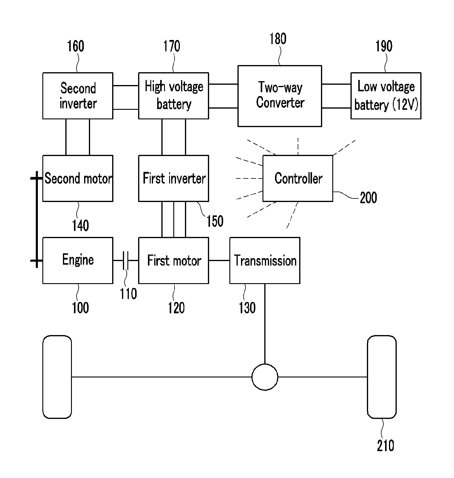
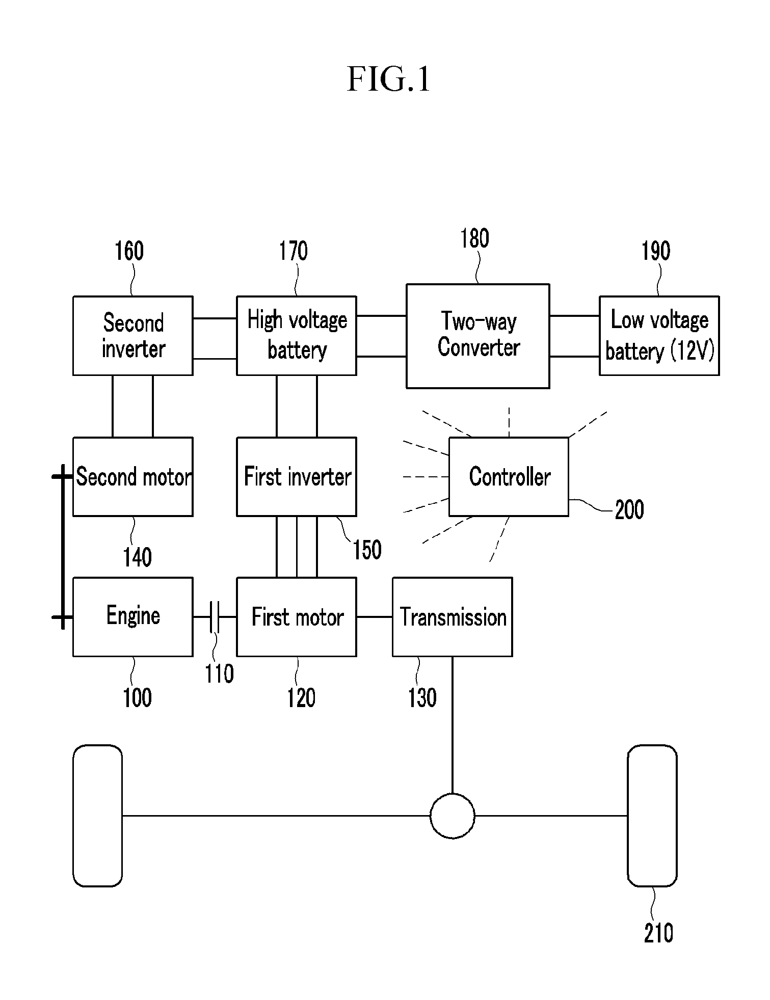
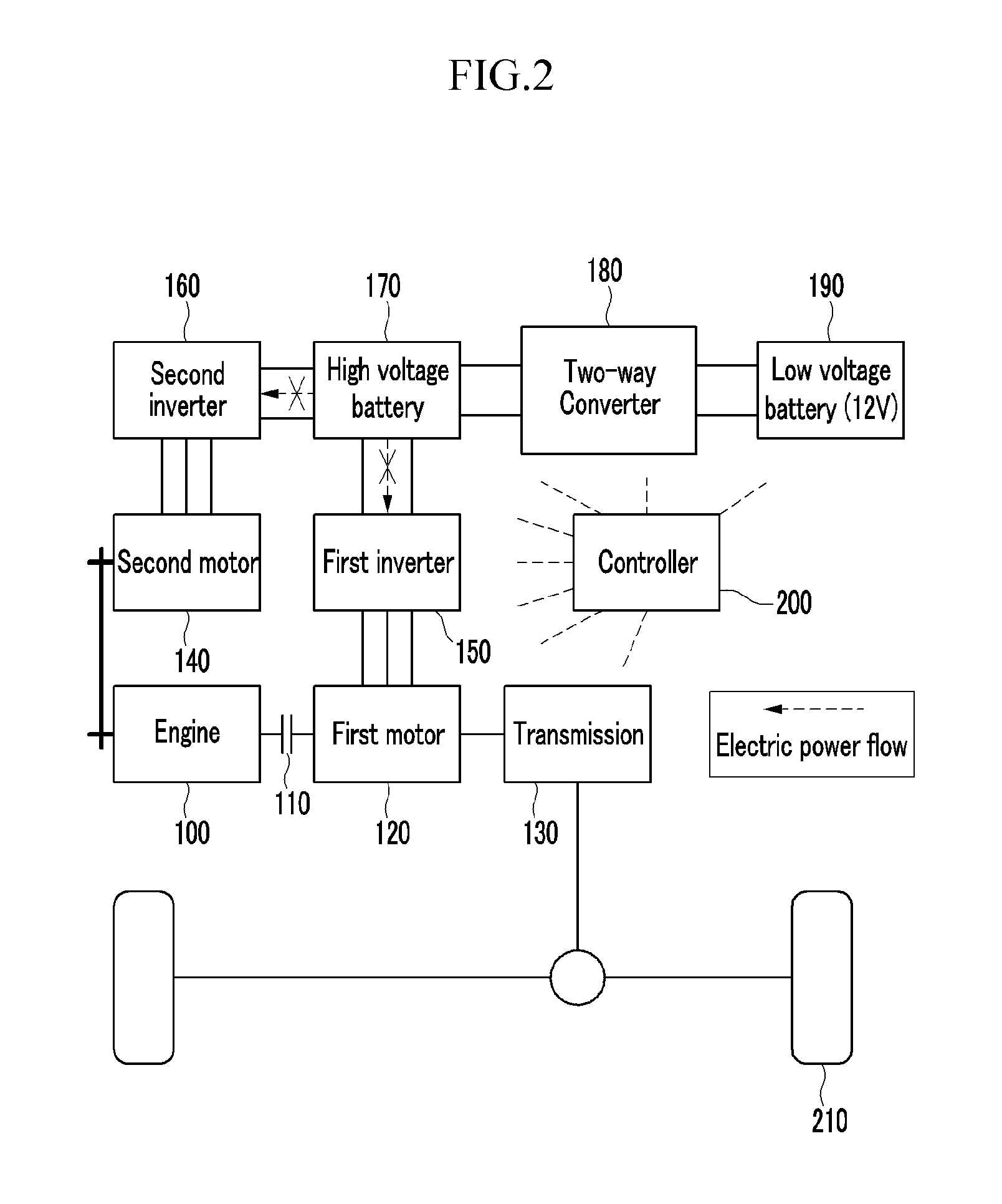
[0028]FIG. 1 is a schematic diagram of a hybrid vehicle according to an exemplary embodiment of the present invention. Referring to FIG. 1, a hybrid vehicle includes an engine 100, a clutch 110, a first motor 120, a transmission 130, a second motor 140, a first inverter 150, a second inverter 160, a high voltage battery 170, a two-way converter 180, a low voltage battery 190, a control portion 200, and a drive wheel 210.

[0029]The first and second motor 120 and 140 can be classified as a motor unit. The first motor is referred to herein also as a main drive motor and the second motor is referred to herein also as a motor / generator. The engine 100, the clutch 110, the first motor 120, and the transmission 130 are sequentially disposed in series. An output shaft of the engine 100 transfers torque to the first motor 120 through the clutch 110, and th...


PUM


Abstract

Disclosed is a system for controlling a hybrid vehicle when the state of charge of a high voltage battery is sufficiently low. In particular, a motor unit is connected to an engine via a rotation element, a high voltage battery is electrically connected to the motor unit to provide power thereto, and a low voltage battery is electrically connected to the high voltage battery through a two-way converter. Advantageously, a control portion is configured to boost voltage of the low voltage battery to supply the high voltage battery with high voltage through the two-way converter when the state of charge of the high voltage battery falls below a first predetermined value.

Description

CROSS-REFERENCE TO RELATED APPLICATION[0001]This application claims priority to and the benefit of Korean Patent Application No. 10-2011-0079055 filed in the Korean Intellectual Property Office on Aug. 9, 2011, the entire contents of which are incorporated herein by reference.BACKGROUND OF THE INVENTION[0002](a) Field of the Invention The present invention relates to a hybrid vehicle in which the output from an engine and a motor are independently controlled according to driving conditions so as to reduce fuel and improve power efficiency of the hybrid vehicle overall.[0003](b) Description of the Related Art[0004]A hybrid vehicle efficiently combines different types of power sources to in order to power a vehicle. Typically, hybrid vehicles combines an engine which generates torque through fuel combustion (gasoline, fossil fuel) and an electric motor that generates torque through battery power.[0005]Hybrid vehicles can run in either an EV (electric vehicle) mode that uses only torqu...

Claims


Application Information

Patent Timeline
IPC IPC(8): H02J7/14B60L50/16
CPCB60K6/28Y02T10/70B60W10/08B60W10/26B60W20/00B60W20/106B60K6/442B60L11/1868B60W2510/244B60W2710/244B60W20/40B60W20/20Y02T10/6286Y02T10/6278Y02T10/6234B60Y2400/112Y02T10/7005Y02T10/7066B60L11/14B60L2210/10Y02T10/7077Y02T10/7216B60W10/06B60W20/13B60L50/16B60L58/20Y02T10/62Y02T10/7072Y02T10/72B60W10/24
Inventor PARK, HYONGJOON
Owner HYUNDAI MOTOR CO LTD
Learn More