System and method for detecting and tracking change in dental x-rays and dental images

a technology of applied in the field of system and method for detecting and tracking changes in dental x-rays, can solve problems such as poor or misaligned bridge work, tooth loss to infection, and the onset of bone loss can be quite sudden

Inactive Publication Date: 2013-02-21
EYEIC
View PDF5 Cites 14 Cited by
  • Summary
  • Abstract
  • Description
  • Claims
  • Application Information

AI Technical Summary

Benefits of technology

[0022]More than two points in time can be compared using the technique of either embodiment above by repeating the above steps and adding the resulting increment of change to the previously documented ones. In this way, a flicker or CIM-based comparison can document many increments of change over an extended period of time.
[0023]In another embodiment of Dental Flicker, photographs and x-rays can be aligned and overlaid allowing dentists and patients to see, for example, the relationship between specific locations on the gum and the teeth or bones beneath the gum. This can be helpful in several ways, for instance allowing dentists and patients to see the relationship between specific spots or conditions of the gum and features which are not normally visible (such as those that can be seen in an x-ray).

Problems solved by technology

Loss of bone density in the upper and lower jaws is a common occurrence in a wide range of dental patients and can cause severe problems ranging from tooth loss to infection.
Causes for bone loss include extracted teeth, poor or misaligned bridge work, trauma and naturally occurring misalignment as well as other factors that prevent the root structures connecting teeth to jaw from being properly stimulated.
Finally, the onset of bone loss can be quite sudden in some circumstances, progressing rapidly in a matter of months.
Left unchecked, the consequences are extreme.
Bone loss can also begin and progress rapidly, making this general lack of awareness all the more problematic.
However, these procedures rely on large, expensive and specialized devices and are not practical in most dental office settings.
Each of these methods has a number of short-comings, however.
For example, using probes requires careful and systematic checking across the mouth at regular intervals, and can be both time consuming and unreliable.
It is also imprecise, and does not lend itself to documentation or tracking X-rays are often difficult to compare due to differences between images arising from parallax, image rotation, image framing or other factors.
Tracking changes in jaw bone volume or density using x-ray comparison is time-consuming and error-prone, especially if differences arising from how the images are captured introduce subtle differences not attributable to bone loss.
Finally, neither periodontal probing nor x-ray comparison is effective in patient education, as probes provide little in the way of visual aids, and x-rays can be difficult for lay people to understand and even more so to compare.

Method used


Image

  • System and method for detecting and tracking change in dental x-rays and dental images
  • System and method for detecting and tracking change in dental x-rays and dental images
  • System and method for detecting and tracking change in dental x-rays and dental images

Examples


first embodiment

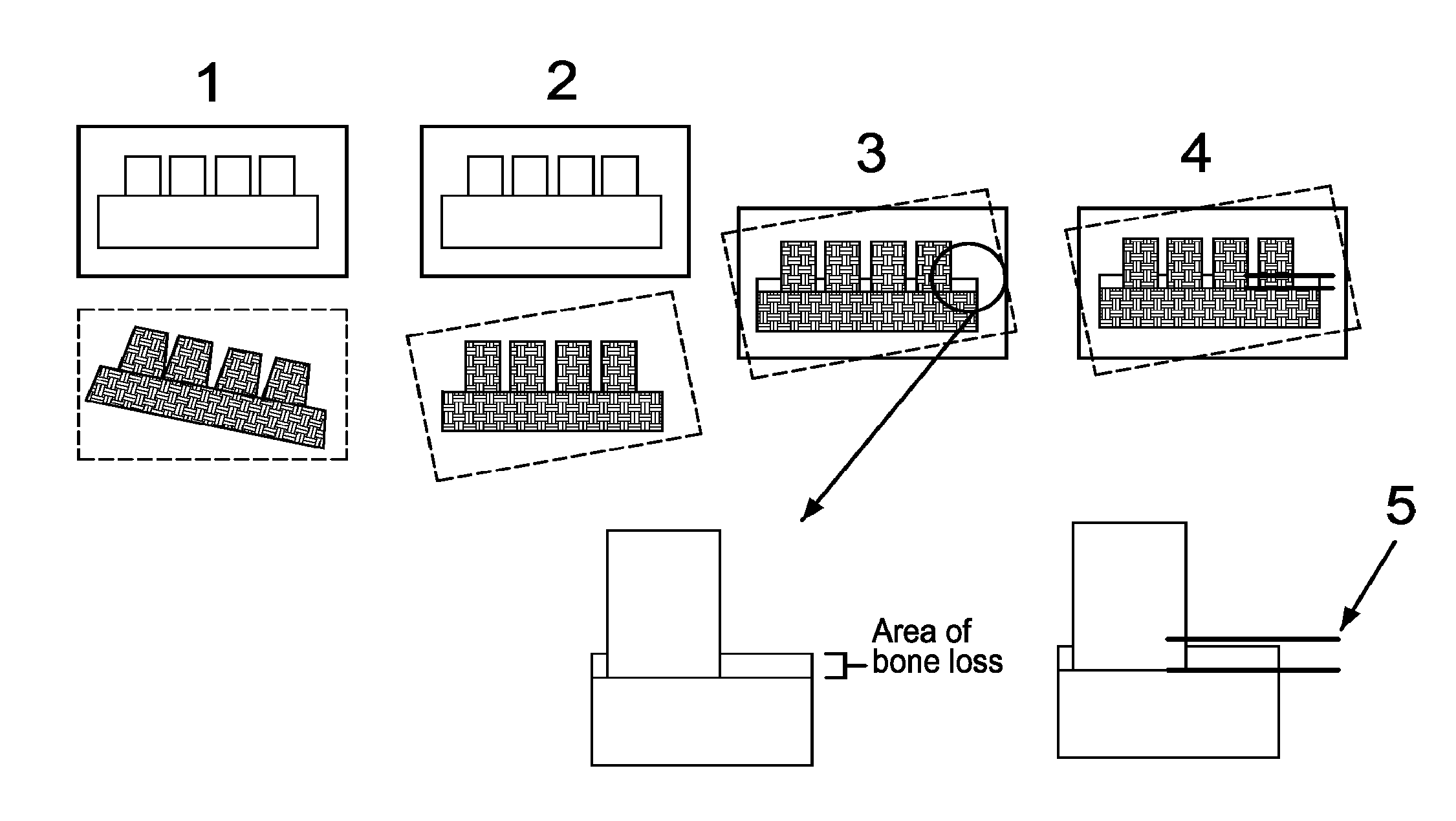
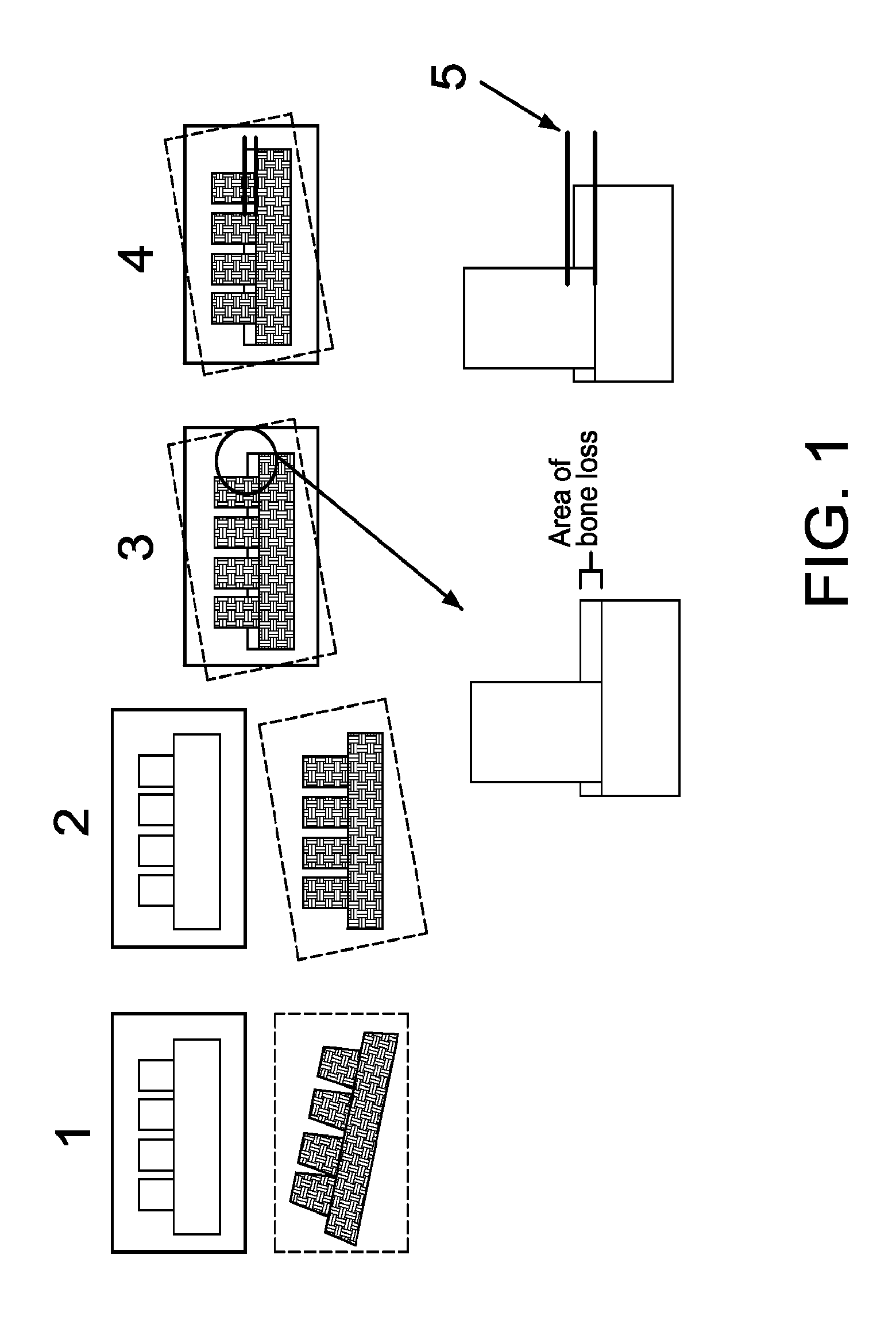
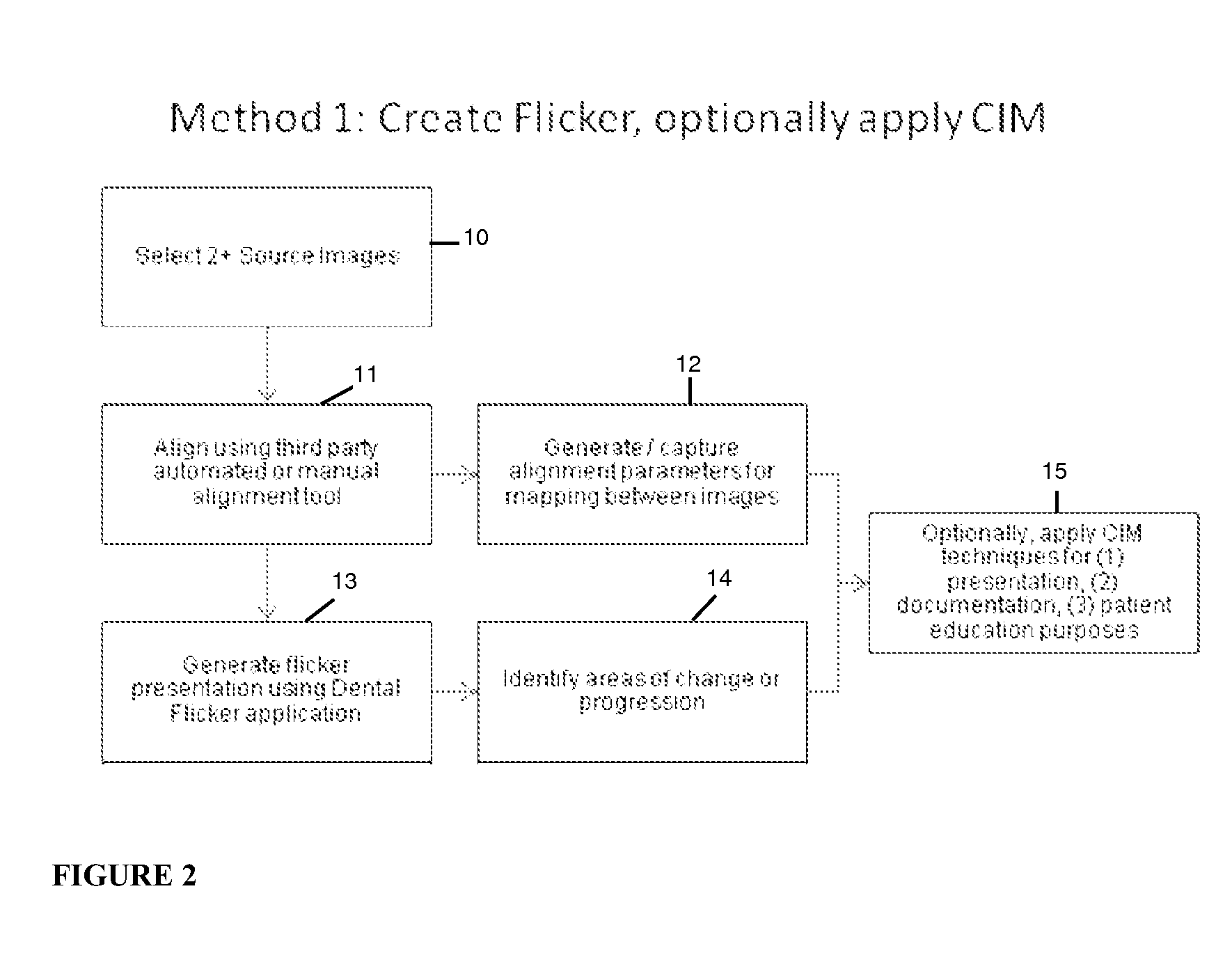
[0035]In accordance with a first embodiment of the invention, computer-aided registration and alignment is used to create a “flicker.” Such a method in accordance with the first embodiment includes establishing a baseline using a historical (existing) x-ray or by creating a new one. Virtually any x-ray (including those from digital sources as well as analog sources which have been scanned) can serve as a baseline, as long as it shows the features or landmarks to be examined, and the perspective, image type and rough image attributes can be approximated in subsequently prepared images. FIG. 1 shows two x-rays of the same area captured from a similar perspective. As illustrated at (1), two source images of the patient from a similar perspective are taken at different points in time, where, in this case, the first image A is taken straight on the tooth and the second image B is taken from a slightly lower perspective of the jaw, with a slight rotation. The technique is most effective w...

second embodiment

[0040]In accordance with a second embodiment of the invention, Cross-Image Mapping (CIM) or comparable techniques are used to apply “before and after” indicators to a single image. Such a method in accordance with the second embodiment allows a DF software user (e.g., a doctor, nurse or technician) to map two or more images using manual or automated registration. These aligned images do not need to be displayed for this technique to be effective, so actual modifications to the image are necessary only if called for by the mapping approach employed. As in the first embodiment, the first step includes acquiring two images of the patient from similar perspectives taken at two different points in time. As illustrated at (1) in FIG. 3, image A is taken straight on and image B is taken from a slightly lower perspective of the jaw with a slight rotation. The images are manually registered by the user as illustrated at (2) in FIG. 3. The CIM module of the DF application then creates formula...

third embodiment

[0043]In accordance with a third embodiment of Dental Flicker techniques, images of different types (for example photos and x-rays) but sharing certain landmarks (for example, teeth) in common, are aligned and / or mapped to allow location of a specific spot in one image on another. For example, this embodiment might be used to allow dentists and patients to relate a specific spot on the gums to the bones and / or teeth below that spot on the gums.

[0044]In such cases it may be necessary to align the images using only selected portions of one or both unaligned (source) images. FIG. 5 illustrates the flickering of two image types, in this case an x-ray and a photograph of the same areas. As illustrated in FIG. 5, the user circles or otherwise identifies the common landmarks (e.g., visible portion of teeth). The system would then align the entire area of the images using only the identified portions as the basis of this alignment. It is noted that the area can be designated in one image (a...


PUM


Abstract

A system and method for detecting and/or rendering easily visible changes in dental images over time so as to identify bone loss, tooth movement, and other forms of change that uses dental images with similar perspectives but taken at different points in time and adjusts one or both of the dental images so as to compensate for differences in perspective, size, and rotation to thereby register the digital images to each other.

Description

CROSS-REFERENCE TO RELATED APPLICATIONS[0001]The present patent application claims priority under 35 U.S.C. §119(e) to U.S. Provisional Patent Application No. 61 / 055,759, filed May 23, 2008. The contents of that patent application are hereby incorporated in their entirety.FIELD OF THE INVENTION[0002]The invention relates to a system and method for detecting and tracking changes in dental x-rays and, more particularly, to a method for any of: (1) detecting bone loss in a patient's jaw, (2) monitoring change and rate of change resulting from normal growth in children and adolescents, (3) tracking and documenting change resulting from the application of braces or other orthodonture, and (4) other forms of change detection and change monitoring. In an alternate embodiment, the invention can be used to overlay two images of differing types (e.g., x-ray and photo).BACKGROUND OF THE INVENTION[0003]Detecting and tracking change has several important applications in dentistry. These include ...

Claims


Application Information

Patent Timeline
Patent Type & Authority Applications(United States)
IPC IPC(8): G06K9/46
CPCA61B6/14A61B6/5235G06T7/0024G06T2207/30036G06K9/6204G06T7/0016G06T2207/10116G06K9/3208G06T7/30G06V10/242G06V10/752
Inventor CALIGOR, DANWALLACE, IRA
Owner EYEIC
Why Eureka
Try Eureka