
Brushless motor driving apparatus and printing apparatus including brushless motor driving apparatus

Inactive Publication Date: 2013-02-28
CANON KK
View PDF1 Cites 10 Cited by
  • Summary
  • Abstract
  • Description
  • Claims
  • Application Information

AI Technical Summary

Benefits of technology

The present invention allows for accurate correction of motor driving errors and improved carriage operation accuracy, even when the mounting position of a Hall element changes or when acceleration and deceleration occur frequently.

Problems solved by technology

This arrangement has many error factors such as a Hall element mounting position error, an unbalanced voltage of the Hall element itself, the hysteresis of the Hall element itself, an offset of a differential amplifier input, the magnetization accuracy of the magnet, and the mechanical decentering of the rotor.
The DC brushless motor inevitably generates errors, such as the dimensional tolerance between building components and the magnetization error of the rotor.
However, when the Hall element switching position is estimated from the timing of an induced voltage generated in a coil, as in the invention of Japanese Patent Laid-Open No. 2009-240041, correction accuracy obtained from the estimation becomes poor in a driving form in which acceleration and deceleration are repeated frequently.

Method used


Image

  • Brushless motor driving apparatus and printing apparatus including brushless motor driving apparatus
  • Brushless motor driving apparatus and printing apparatus including brushless motor driving apparatus
  • Brushless motor driving apparatus and printing apparatus including brushless motor driving apparatus

Examples


modification to embodiment

[0083]In FIG. 4, one output from the D / A converter is the reference voltage, and the other is the reference voltage+correction value. As a modification, as shown in FIG. 13, an arrangement in which one output from the D / A converter is the reference voltage+correction value 1 and the other is the reference voltage+correction value 2 to adjust the commutation timing is also possible.

[0084]In FIG. 4, one output from the D / A converter is the reference voltage, and the other is the reference voltage+correction value. Alternatively, addition of the reference voltage may be stopped in accordance with a circuit which processes a signal.

[0085]The Hall element itself has a hysteresis, and the differential amplifier also has a hysteresis for noise removal. For this reason, the timing of commutation by forward / reverse rotation of the rotor changes. Considering this, correction values are acquired individually in forward rotation and reverse rotation, taking appropriate measures for both of the ...

application of embodiment

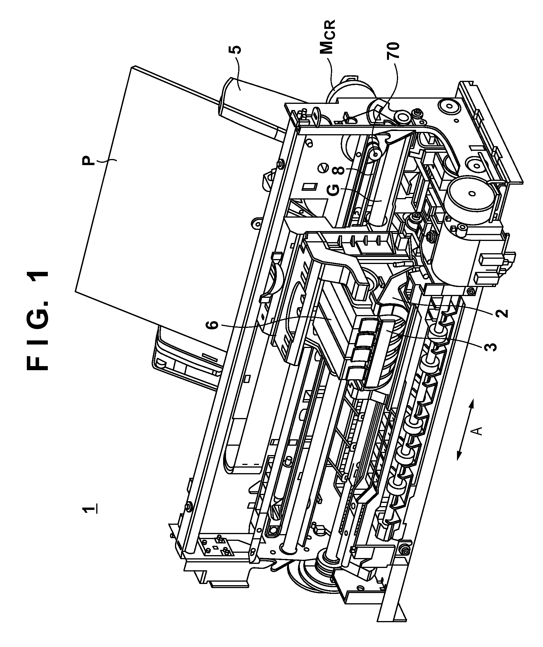
[0089]The embodiment has explained carriage driving of an ink-jet printer. However, the present invention is also applicable to a motor driving apparatus for conveying a printing medium as long as the commutation interval can be measured and calculated to provide a correction output in a general multiphase driving brushless motor. The present invention is applicable not only to an ink-jet printer but also to an electrophotographic printer and another device such as a scanner (image reading apparatus).

Other Embodiments

[0090]Aspects of the present invention can also be realized by a computer of a system or apparatus (or devices such as a CPU or MPU) that reads out and executes a program recorded on a memory device to perform the functions of the above-described embodiment(s), and by a method, the steps of which are performed by a computer of a system or apparatus by, for example, reading out and executing a program recorded on a memory device to perform the functions of the above-desc...


PUM


Abstract

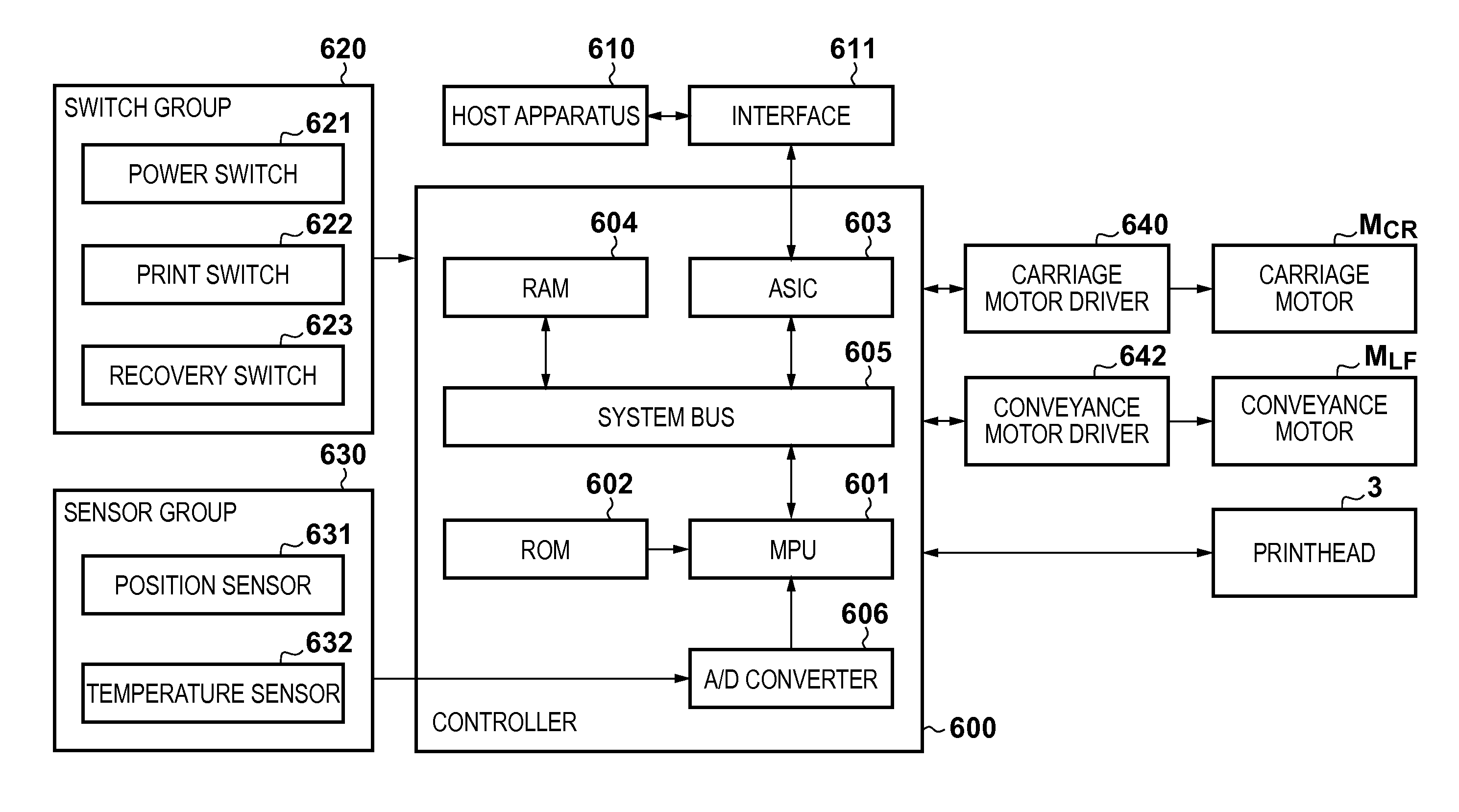
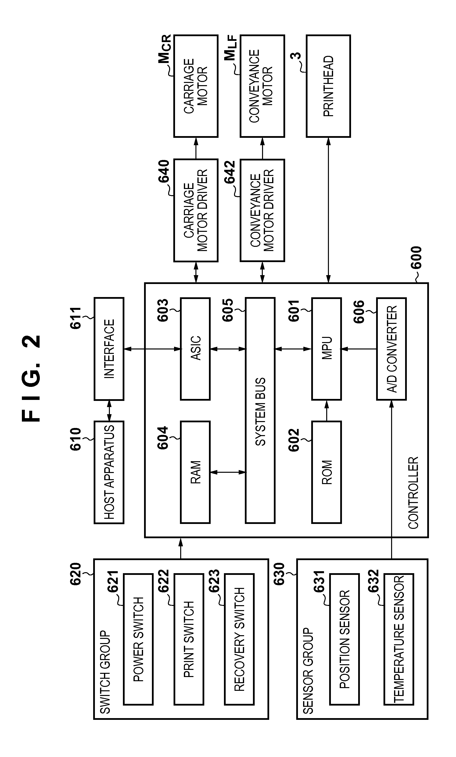
The operation accuracy of a printing unit is improved in a printing apparatus. To accomplish this, a motor driving apparatus comprise a brushless motor including coils of a plurality of phases, and a plurality of detection units that output voltages in accordance with rotation of a rotor, a driving unit that drives the brushless motor by switching a current supply destination between the coils of the plurality of phases based on a control signal, and a generation unit that generates the control signal based on addition results of detection signals output from the plurality of detection units, and correction signals based on differences between a predetermined voltage corresponding to a rotation angle of the rotor and voltages corresponding to the rotation angle of the rotor that are obtained from the plurality of detection units.

Description

BACKGROUND OF THE INVENTION[0001]1. Field of the Invention[0002]The present invention relates to a brushless motor driving apparatus and a printing apparatus including the brushless motor driving apparatus and, more particularly, to a DC brushless motor driving technique of driving a carriage on which a printhead is mounted.[0003]2. Description of the Related Art[0004]Recently, printing apparatuses require higher image qualities. Possible measures are, for example, to increase the printing medium conveyance accuracy, the printhead printing accuracy (for example, for an ink-jet printer, ink discharge amount and discharge timing), and the operation accuracy of the carriage on which the printhead is mounted.[0005]Of these measures, attention is paid to the carriage operation accuracy. An ink-jet printer or the like simultaneously performs carriage operation control and printhead printing control, because the printhead prints while the carriage operates. Hence, the carriage operation ac...

Claims


Application Information

Patent Timeline
IPC IPC(8): H02P6/16B41J29/38B41J19/18H02P6/06H02P6/08
CPCB41J29/38B41J29/02H02P6/16
Inventor SOHARA, YOSHITSUGU
Owner CANON KK
Learn More