
Amplification systems and methods with distortion reductions

a technology of distortion reduction and amplifier, applied in the field of integrated circuits, can solve problems such as the instability of amplifier b>118/b>

Active Publication Date: 2013-03-07
ON BRIGHT ELECTRONICS SHANGHAI
View PDF9 Cites 19 Cited by
  • Summary
  • Abstract
  • Description
  • Claims
  • Application Information

AI Technical Summary

Benefits of technology

The present invention provides a system for reducing distortion in amplification systems. The system includes a first integrator and a second integrator that receive an input signal and generate an integrated signal based on the input signal. A compensation capacitor is coupled to the first and second integrators and a switch that receives a control signal. The system also includes a modulation and drive component that receives the integrated signal and generates an output signal. The technical effect of the invention is to reduce distortion in amplification systems.

Problems solved by technology

The phase margin is 0°, and thus the amplifier 118 is often unstable.
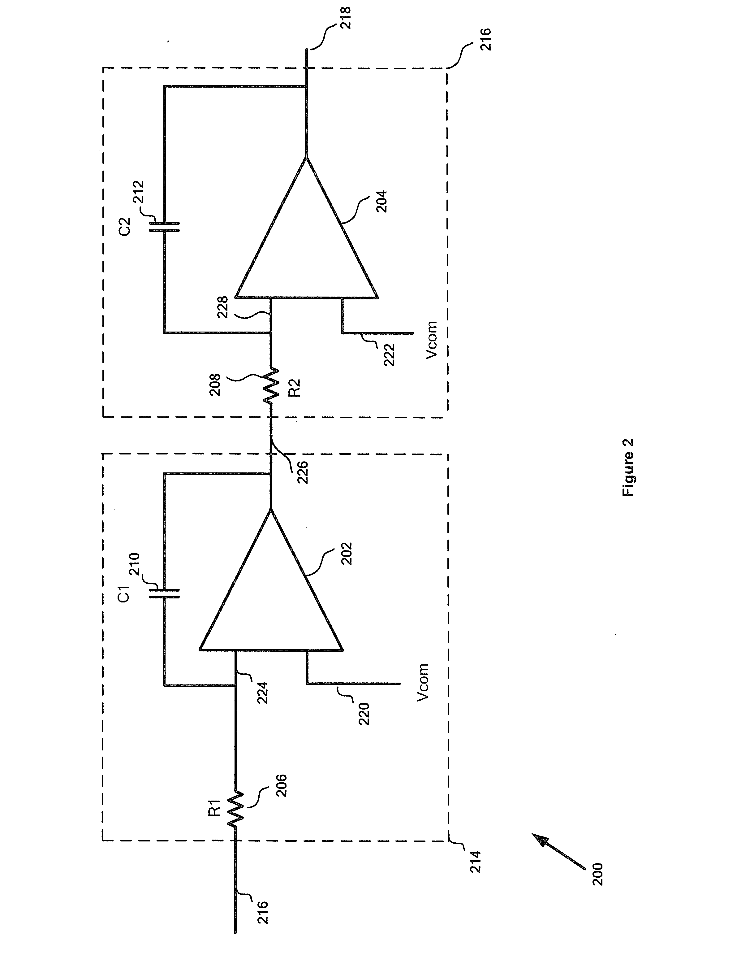
Furthermore, the saturation of the integrator 200 often causes distortion. FIG. 4 is a simplified conventional timing diagram of the input audio signal 120.

Method used


Image

  • Amplification systems and methods with distortion reductions
  • Amplification systems and methods with distortion reductions
  • Amplification systems and methods with distortion reductions

Examples


Embodiment Construction

[0032]The present invention is directed to integrated circuits. More particularly, the invention provides distortion reductions to amplification systems. Merely by way of example, the invention has been applied to a Class-D amplifier. But it would be recognized that the invention has a much broader range of applicability.

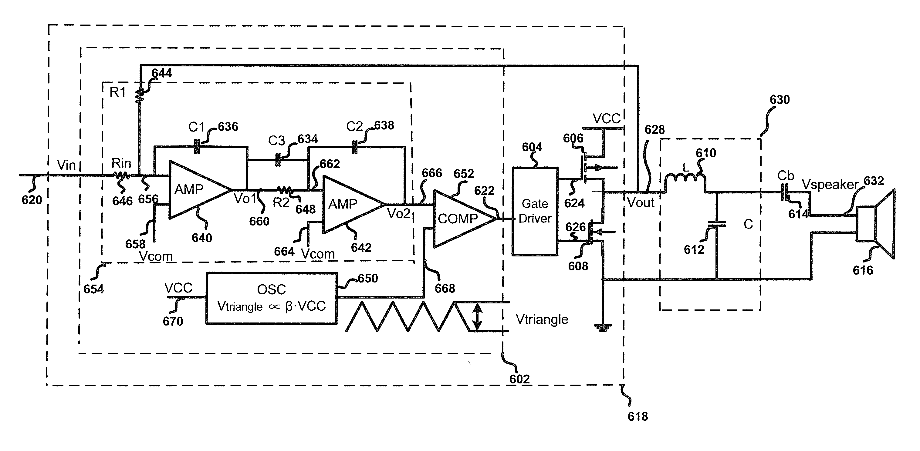
[0033]FIG. 6 is a simplified diagram showing an amplification system according to one embodiment of the present invention. This diagram is merely an example, which should not unduly limit the scope of the claims. One of ordinary skill in the art would recognize many variations, alternatives, and modifications.

[0034]The amplification system 600 includes a gate driver 604, two transistors 606 and 608, an inductor 610, two capacitors 612 and 614, and an output load 616. Further, the amplification system 600 includes three capacitors 634, 636 and 638, two operational amplifiers 640 and 642, three resistors 644, 646 and 648, a signal generator 650, and a comparator 652.

[...


PUM


Abstract

System and method for integrating an input signal to generate an output signal. The system includes a first integrator configured to receive the input signal and generate an integrated signal based on at least information associated with the input signal, a second integrator configured to receive the integrated signal and generate the output signal based on at least information associated with the integrated signal, and a compensation capacitor coupled to the first integrator and the second integrator. The first integrator includes a first integration capacitor and a first operational amplifier including a first input terminal and a first output terminal, the first integration capacitor being coupled between the first input terminal and the first output terminal. The second integrator includes a second integration capacitor and a second operational amplifier including a second input terminal and a second output terminal.

Description

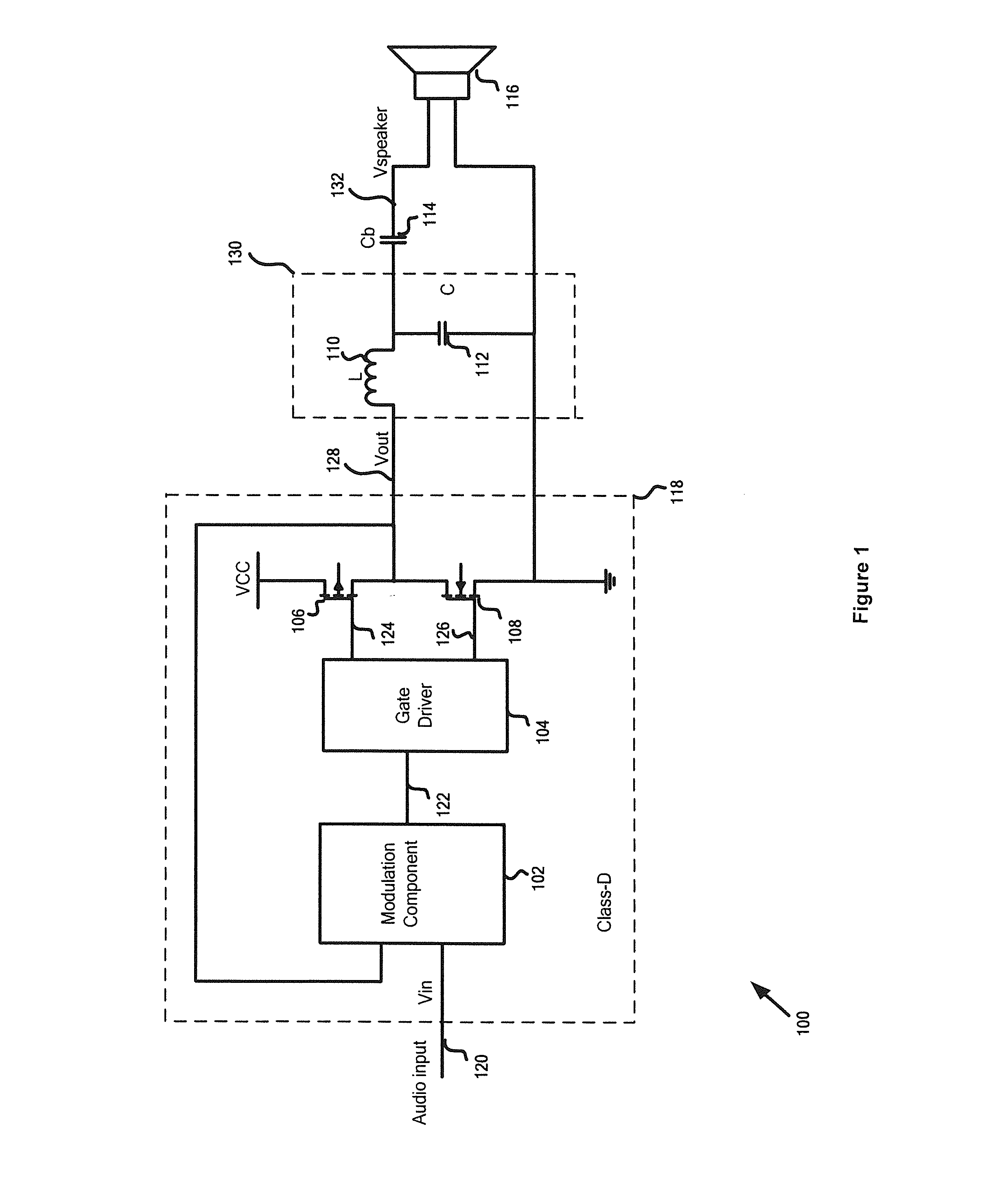
1. CROSS-REFERENCES TO RELATED APPLICATIONS[0001]This application claims priority to Chinese Patent Application No. 201110268690.5, filed Sep. 6, 2011, commonly assigned, incorporated by reference herein for all purposes.2. BACKGROUND OF THE INVENTION[0002]The present invention is directed to integrated circuits. More particularly, the invention provides distortion reductions to amplification systems. Merely by way of example, the invention has been applied to a Class-D amplifier. But it would be recognized that the invention has a much broader range of applicability.[0003]Usually, a switching amplifier (e.g., a Class-D amplifier) is an amplifier where output transistors are often operated as switches. The Class-D amplifier is widely used in audio amplification, and has power-efficiency advantages over certain linear audio-amplifier classes such as Class A, B, and AB.[0004]FIG. 1 is a simplified conventional diagram showing an amplification system using a Class-D amplifier. The ampl...

Claims


Application Information

Patent Timeline
IPC IPC(8): G06G7/186
CPCH04R2430/01H04R3/04H03F1/3205H03F3/183H03F2200/03H03F2201/3215
Inventor YUAN, TINGZHIZHANG, YUNCHAOSUN, ZHIQIANGFANG, LIEYI
Owner ON BRIGHT ELECTRONICS SHANGHAI
Learn More