Imaging lens

a technology of imaging lens and spherical lens, which is applied in the field of imaging lens, can solve the problems of difficult to meet the optical performance requirements of such a two- or three-lens configuration, difficulty in sufficiently correcting aberration anymore, and limited abbe's number of first and second lenses, so as to achieve satisfactory image-forming performance, small maximum emitting angle of off-axis light beam, and easy shading

Active Publication Date: 2013-03-07
TOKYO VISIONARY OPTICS CO LTD
View PDF9 Cites 28 Cited by
  • Summary
  • Abstract
  • Description
  • Claims
  • Application Information

AI Technical Summary

Benefits of technology

[0011]Here, according to the imaging lens having the above-described configuration, preferably, each lens of the first lens and lenses from the third to the fifth lenses has the same Abbe's number and is made of the same material. With this configuration, it is possible to suitably attain productivity improvement and manufacturing cost reduction of the imaging lens. In addition, forming each lens from the first lens to the fifth lens from a plastic material, it is possible to further attain productivity improvement and manufacturing cost reduction.
[0013]When the imaging lens satisfies the conditional expressions (1) and (2), it is possible to satisfactorily correct aberrations while attaining miniaturization of the imaging lens. When the imaging lens satisfies the conditional expressions (1) and (2), the first lens and the second lens, which are arranged on the object side, have stronger refractive power than other three lenses. With the configuration, it is possible to shorten a total optical length of the imaging lens while securing certain angle of view, and it is possible to suitably attain miniaturization of the imaging lens. In addition, according to the invention, each lens from the third lens to the fifth lens has relatively weak refractive power. Aberrations occurred in the first lens and the second lens, which have strong refractive powers, are suitably corrected through each lens from the third lens to the fifth lens, which have weak refractive powers.
[0025]Therefore, restraining the maximum sag within certain range, the third lens and the fourth lens are formed in shapes that have substantially uniform thickness in the optical axis direction and are less curved. With such shapes of the third and the fourth lenses, generation of complicated aberrations is restrained and aberrations occurred in the first and the second lenses are satisfactorily corrected. Furthermore, sensitivity to deterioration of the image-forming performance due to decentering (axial displacement), tilting, or the like upon manufacturing the imaging lens, i.e., so-called “production error sensitivity” decreases. In addition, because of the substantially uniform thickness in the optical axis direction, fabrication properties upon production are improved and manufacturing cost of the imaging lens is restrained. Here, “sag” means, in each surface, a distance in a direction parallel to the optical axis from a tangential plane that is orthogonal to the optical axis to the surface.
[0030]When the imaging lens satisfies the conditional expression (9), it is possible to keep the maximum emitting angle of an off-axis light beam small, while attaining miniaturization of the imaging lens. When the value exceeds the upper limit “1.5”, although it is easy to keep the maximum emitting angle of the off-axis light beam small, it is difficult to attain miniaturization of the imaging lens. On the other hand, when the value is below the lower limit “0.3”, although it is advantageous for miniaturization of the imaging lens, a chromatic aberration is insufficiently corrected and it is difficult to obtain satisfactory image-forming performance. In addition, since the maximum emitting angle of an off-axis light beam is large, the shading phenomenon easily occurs.
[0031]According to the imaging lens of the invention, it is possible to attain both miniaturization and satisfactory aberration correction of the imaging lens and provide a small-sized imaging lens with satisfactorily corrected aberrations.

Problems solved by technology

However, optical performances required for such a high-resolution imaging element have been increased each year, so that it is difficult to sufficiently correct aberrations anymore.
Further, it is difficult to meet those optical performance requirements with such a two- or three-lens configuration.
In addition, there are limitations in a lower limit of Abbe's number of the first lens and an upper limit of Abbe's number of the second and the fourth lenses.
However, since the total length of the lens system is long, it is difficult to attain both miniaturization of the imaging lens and satisfactory aberration correction.
Here, such challenge of attaining both miniaturization and satisfactory aberration correction is not specific to the imaging lens for mounting in a cellular phone, but common among imaging lenses for mounting in relatively small cameras such as digital still cameras, portable information terminals, security cameras, onboard cameras, and network cameras.

Method used


Image

  • Imaging lens
  • Imaging lens
  • Imaging lens

Examples


Embodiment Construction

[0047]Hereunder, referring to the accompanying drawings, an embodiment of the present invention will be fully described.

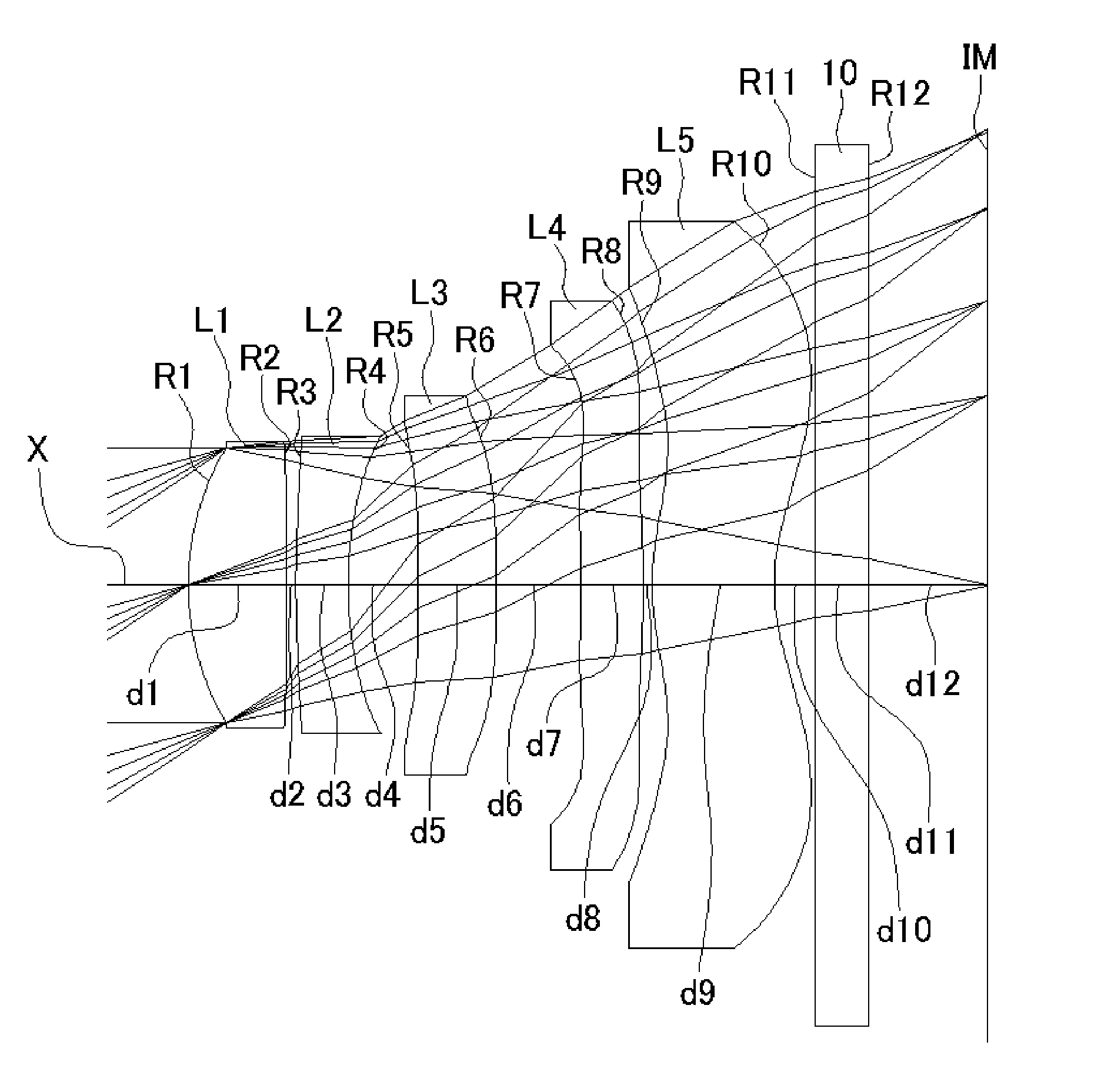
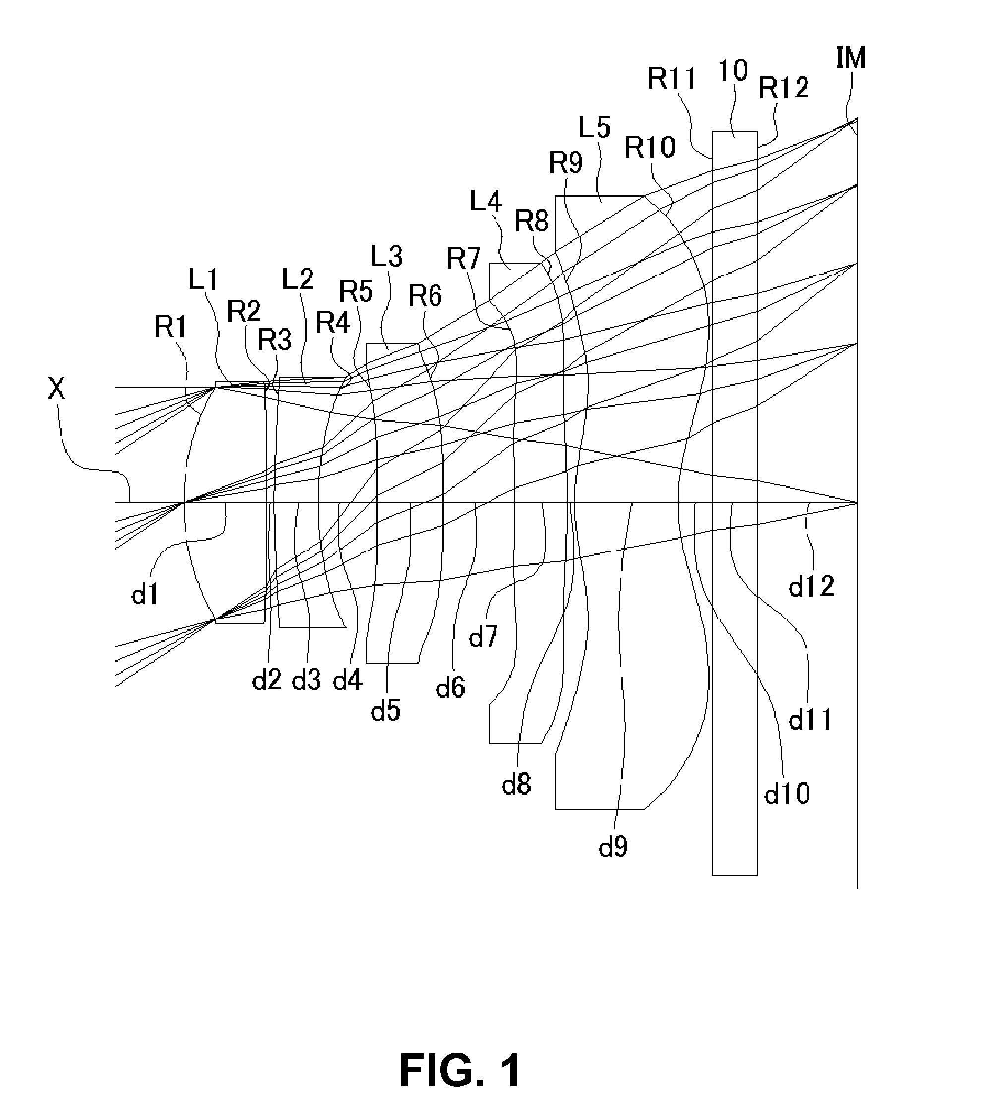
[0048]FIGS. 1, 4, 7, 10, and 13 are schematic sectional views of imaging lenses in Numerical Data Examples 1 to 5 according to the embodiment, respectively. Since a basic lens configuration is the same among those Numerical Data Examples, the lens configuration of the embodiment will be described with reference to the schematic sectional view of Numerical Data Example 1.

[0049]As shown in FIG. 1, the imaging lens of the embodiment includes a first lens L1 having positive refractive power, a second lens L2 having negative refractive power, a third lens L3 having positive refractive power, a fourth lens L4 having negative refractive power, and a fifth lens L5 having negative refractive power, arranged in the order from an object side to an image plane side. A filter 10 such as an infrared cut-off filter or a cover glass may be provided between the fifth lens L5 and an...


PUM


Abstract

An imaging lens includes a first lens having positive refractive power; a second lens having negative refractive power; a third lens having positive refractive power; and a fourth and a fifth lens having negative refractive power. The first lens is formed so that a curvature radius of an object-side surface is positive and the second lens is formed so that a curvature radius of an object-side surface and a curvature radius of an image plane-side surface are positive. The third lens is formed so that a curvature radius of an object-side surface is positive, and the fifth lens is formed so that a curvature radius of an object-side surface and a curvature radius of an image plane-side surface are both positive. An Abbe's number from the first and the third to the fifth lens is greater than 45, and an Abbe's number of the second lens is less than 35.

Description

BACKGROUND OF THE INVENTION AND RELATED ART STATEMENT[0001]The present invention relates to an imaging lens for forming an optical image on an imaging element such as a CCD sensor and a CMOS sensor. Particularly, the present invention relates to an imaging lens suitable for mounting in a relatively small camera such as a cellular phone, a digital still camera, a portable information terminal, a security camera, an onboard camera, and a network camera.[0002]Performances of a camera mounted in a cellular phone have been improved every year, and there is even a camera having optical performances comparable to those of a digital still camera. The resolution of an imaging element that used to be several hundred thousand pixels has been improved to several megapixels, and the resolution of a camera has been dramatically improved. An imaging lens for mounting in such camera needs to not only have a small size, but also have resolution comparable to that of a high-resolution imaging element...

Claims


Application Information

Patent Timeline
Patent Type & Authority Applications(United States)
IPC IPC(8): G02B9/60
CPCG02B13/0045G02B13/18G02B9/60G02B13/0015
Inventor KUBOTA, YOJIKUBOTA, KENICHIHIRANO, HITOSHIKURIHARA, ICHIROISE, YOSHIOYONEZAWA, TOMOHIRO
Owner TOKYO VISIONARY OPTICS CO LTD
Why Eureka
Try Eureka